Tube bending machine

a tube bending machine and man-operated technology, applied in the field of man-operated tube bending machines, can solve the problems of not having a large amount of floor space, not having a large amount of unobstructed space, and not having a continuous bend of about 30°,

Active Publication Date: 2011-05-05
JPW IND
View PDF7 Cites 23 Cited by
  • Summary
  • Abstract
  • Description
  • Claims
  • Application Information

AI Technical Summary

Problems solved by technology

The problem with this design is that the larger or more rigid the workpiece, the long lever need to be and the more unobstructed floor space was needed to operate the device.
The problem with this design is that the linear ratchet had a length of about 18 inches, and could only produce a continuous bend of about 30°.
When the workpiece was being bent 180°...

Method used


Image

  • Tube bending machine
  • Tube bending machine
  • Tube bending machine

Examples


Embodiment Construction

While this invention is susceptible of embodiment in many different forms, the drawings show and the specification describes in detail a preferred embodiment of the invention. It should be understood that the drawings and specification are to be considered an exemplification of the principles of the invention. They are not intended to limit the broad aspects of the invention to the embodiment illustrated.

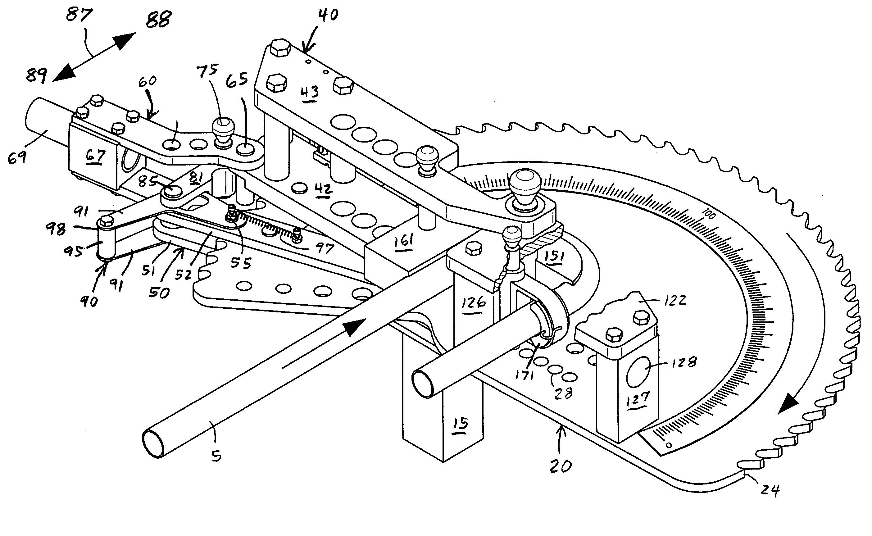
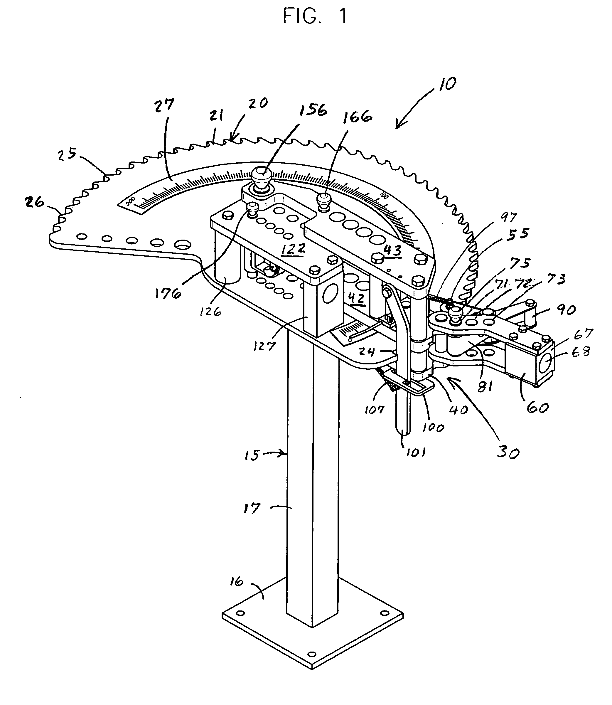
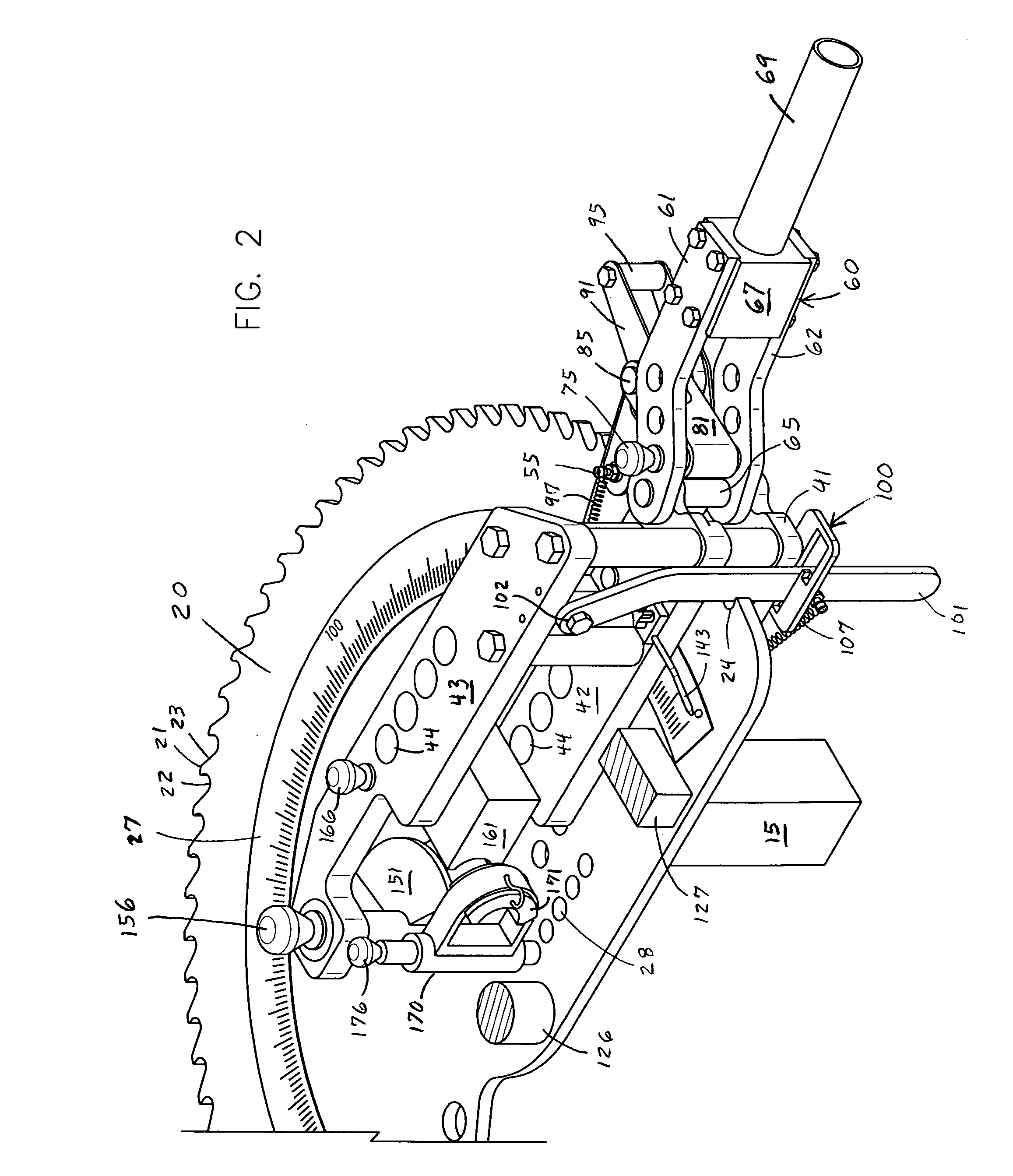
The present invention generally relates to a manually operated tube bending machine generally shown by reference number 10. The tube bending machine 10 is mounted on a stationary pedestal 15. The pedestal includes an anchor plate 16 that is firmly secured by bolts or otherwise to the floor of a building, or some other fixed structure. An integral riser 17 extends upwardly from the anchor plate 16. The riser 17 supports a stationary upper mounting plate 18. The mounting plate 18 forms a generally horizontal surface for mounting the working components of the tube bending machine 10 at...


PUM

PropertyMeasurementUnit
Lengthaaaaaaaaaa
Speedaaaaaaaaaa
Shapeaaaaaaaaaa

Abstract

This invention is a manually operated tube bending machine with a power drive mechanism that is adjustably set to a desired bend speed. The bending machine includes a bending die, a counter die and a rotating hook die to form a desired bend into a tube or pipe. The tube bender includes a drive wheel with ratchet teeth around its perimeter. A drive pin grips one of the ratchet teeth. The drive pin is secured to a lever and torque bar. During each bending stroke, the lever and torque bar incrementally rotate the drive wheel a desired amount. The rotation of the drive wheel and hook die draw the tube through the bending and counter dies to bend the tube. An anti-spring back mechanism holds the position of the drive wheel while the power drive mechanism is advanced to grip the next ratchet tooth of the drive wheel.

Description

TECHNICAL FIELD OF THE INVENTIONThis invention relates to a manually operated tube bending machine with a variable speed drive.BACKGROUND OF THE INVENTIONManually operated tube benders rely on human power and leverage to bend a workpiece such as a tube, pipe or rod. The manual tube bender is typically secured to the floor or another fixed structure. In the 1930s, a manual bender was developed that fixed the workpiece to the bender, and used a long lever to bend the workpiece. The problem with this design is that the larger or more rigid the workpiece, the long lever need to be and the more unobstructed floor space was needed to operate the device. In the 1980s, a manual tube bender was introduced that included a linear ratchet device to multiply the force of the lever. The problem with this design is that the linear ratchet had a length of about 18 inches, and could only produce a continuous bend of about 30°. Then, the workpiece had to be removed and realigned on the bender. In man...

Claims


Application Information

Patent Timeline
IPC IPC(8): B21D11/00
CPCB21D7/14B21D7/063
Inventor RUSCH, CHRISTOPHER J.
Owner JPW IND
Why Eureka
Try Eureka