Cryogenic system and method for superconducting magnets

a cryogenic system and magnet technology, applied in the field of cryogenic systems for superconducting magnets, can solve the problems of large amount of cryogenic gas that vents to the atmosphere, detrimental effects of stray magnetic fields, loss,

Active Publication Date: 2011-05-05
GENERAL ELECTRIC CO
View PDF20 Cites 20 Cited by
  • Summary
  • Abstract
  • Description
  • Claims
  • Application Information

AI Technical Summary

Problems solved by technology

Such mounting of the cooling coldhead to the superconducting magnet has several disadvantages including the detrimental effects of stray magnetic fields on the coldhead motor, vibration transmission from the coldhead to the superconducting magnet, and temperature gradients along the thermal connections between the coldhea...

Method used


Image

  • Cryogenic system and method for superconducting magnets
  • Cryogenic system and method for superconducting magnets
  • Cryogenic system and method for superconducting magnets

Examples


Embodiment Construction

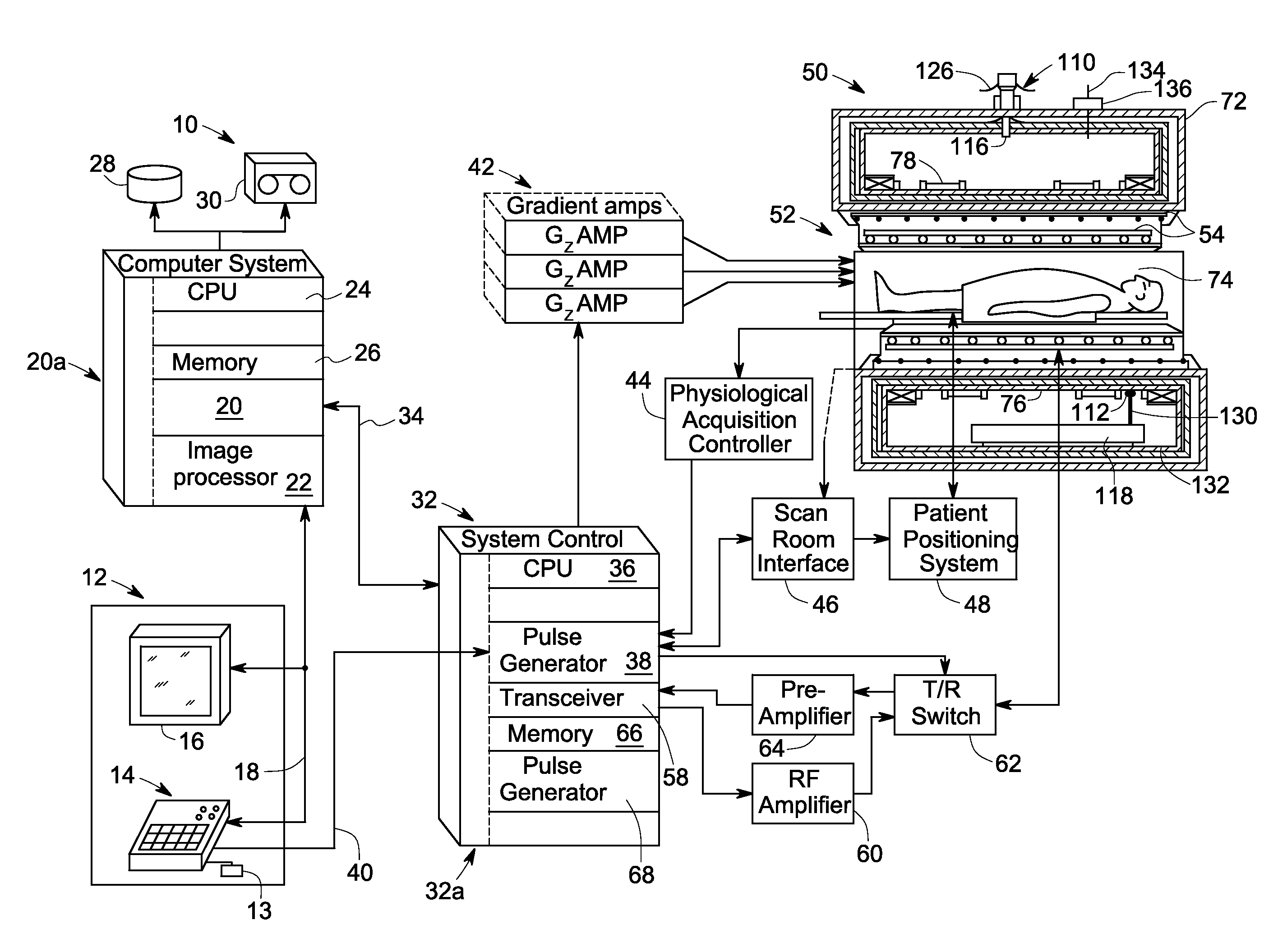
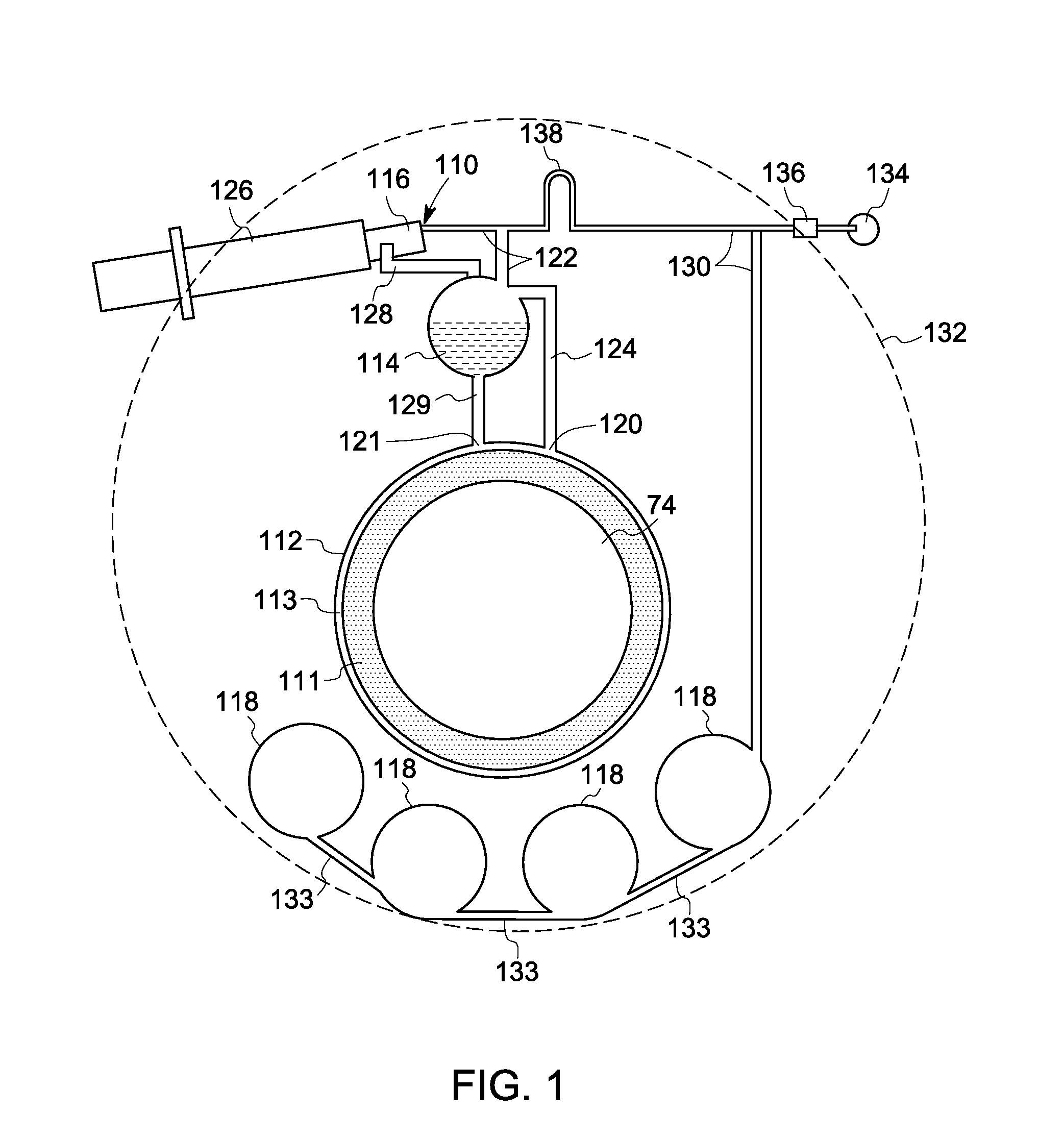
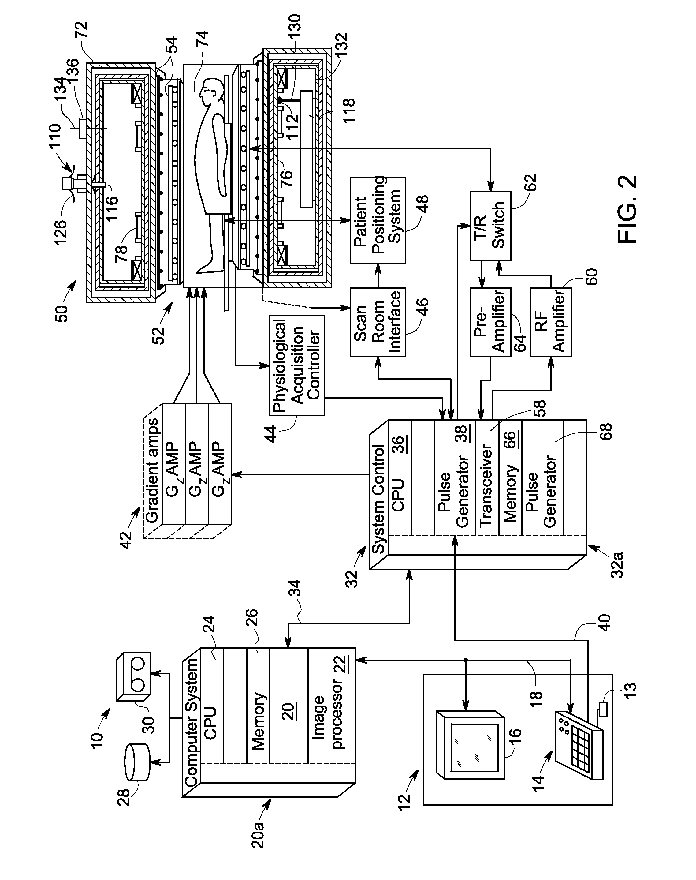
[0014]Embodiments of the invention relate to a cryogenic system for a superconducting magnet. The cryogenic system comprises at least one closed-loop cooling path, and the closed-loop cooling path comprises at least one cooling tube thermally coupled to the superconducting magnet, a re-condenser fluidly coupled to the magnet cooling tube through tube sections and associated with a refrigerator, at least one liquid cryogen container fluidly coupled between the magnet cooling tube and the re-condenser, and at least one gas tank fluidly coupled to the magnet cooling tube through a connection tube. A cryogen flows in the closed-loop cooling path, which comprises a liquid cryogen flowing through at least a portion of the magnet cooling tube, and a gaseous cryogen vaporized from the liquid cryogen.

[0015]Referring to FIG. 1, an exemplary cryogenic system 110 for cooling a superconducting magnet 111 is illustrated, which is very exaggerated for purposes of illustration and is not drawn to s...


PUM


Abstract

A cryogenic system for a superconducting magnet comprises a closed-loop cooling path. The closed-loop cooling path comprises a magnet cooling tube thermally coupled to the superconducting magnet. The magnet cooling tube comprises a cryogen flow passage. The closed-loop cooling tube further comprises a re-condenser is fluidly coupled to the magnet cooling tube through tube sections and a liquid cryogen container fluidly coupled between the magnet cooling tube and the re-condenser. At least one gas tank is fluidly coupled to the magnet cooling tube through a connection tube.

Description

BACKGROUND[0001]1. Technical Field[0002]Embodiments of the invention relate to a cryogenic system for superconducting magnets.[0003]2. Discussion of Related Art[0004]Superconducting magnets conduct electricity without resistance as long as magnets are maintained at a suitably low temperature, which is referred to as “superconducting temperature” herein after. Accordingly, cryogenic systems are used to ensure that the superconducting magnets work below the superconducting temperature.[0005]One conventional cryogenic system uses a cooling coldhead which is mounted to the superconducting magnet. Such mounting of the cooling coldhead to the superconducting magnet has several disadvantages including the detrimental effects of stray magnetic fields on the coldhead motor, vibration transmission from the coldhead to the superconducting magnet, and temperature gradients along the thermal connections between the coldhead and the superconducting magnet.[0006]Another conventional cryogenic syst...

Claims


Application Information

Patent Timeline
IPC IPC(8): G01R33/44F25B19/00F17C5/02
CPCF25B2400/17G01R33/3815G01R33/3804F25D19/00F25B9/00
Inventor HUANG, XIANRUIZHAO, YANZHANG, TAOWU, ANBOLASKARIS, EVANGELOS TRIFONTHOMPSON, PAUL ST. MARK SHADFORTH
Owner GENERAL ELECTRIC CO
Why Eureka
Try Eureka