
Migration-based illumination determination for ava risk assessment

Active Publication Date: 2011-05-05
BP CORP NORTH AMERICA INC
View PDF4 Cites 32 Cited by
  • Summary
  • Abstract
  • Description
  • Claims
  • Application Information

AI Technical Summary

Benefits of technology

[0019]Thus, remigration of a demigrated or modeled data set produced according to the instant invention then produces a gather on which any amplitude variation is more likely to be a measure of illumination effects alone. The resulting AVA signature on the gather can then be used to help distinguish whether amplitude variation on the angle gathers is due to illumination effects during propagation, or actual rock properties. This approach also preferably produces an AVA confidence analysis which can help the explorationist determine when AVA signatures are relatively free from illumination effects.

Problems solved by technology

However, deeper targets pose a number of problems for this technology, not the least of which is related to the distortion that may be introduced by the subsurface structure and / or the processing methods that are used to image that structure.
Since AVA is often used to assess the potential for well location, any irregularities in AVA response due to uneven acoustic illumination resulting from complex overburden introduces substantial risk in AVA analysis and could very well adversely effect well placement.
Subsurface imaging in regions of complex structure is problematic because the seismic wavefield may be distorted significantly as it passes through such complexity.
Seismic surveys that include subsurface salt features (e.g., salt domes) can produce data that is marred by uneven illumination of the reflectors below the salt (or other structure).
This in turn, can cause AVA-type analyses to be difficult to interpret and / or simply unreliable.
This velocity contrast results in large amounts of ray bending and rays that are normal to the target reflector will tend to go critical at the sediment salt interface.
Conventional seismic imaging methods do not properly compensate for this uneven illumination, which can distort the observed trace amplitudes and can render AVO / AVA analysis unreliable.

Method used


Image

  • Migration-based illumination determination for ava risk assessment
  • Migration-based illumination determination for ava risk assessment
  • Migration-based illumination determination for ava risk assessment

Examples


Embodiment Construction

[0028]While this invention is susceptible of embodiment in many different forms, there is shown in the drawings, and will herein be described hereinafter in detail, some specific embodiments of the instant invention. It should be understood, however, that the present disclosure is to be considered an exemplification of the principles of the invention and is not intended to limit the invention to the specific embodiments or algorithms so described.

General Environment of the Invention

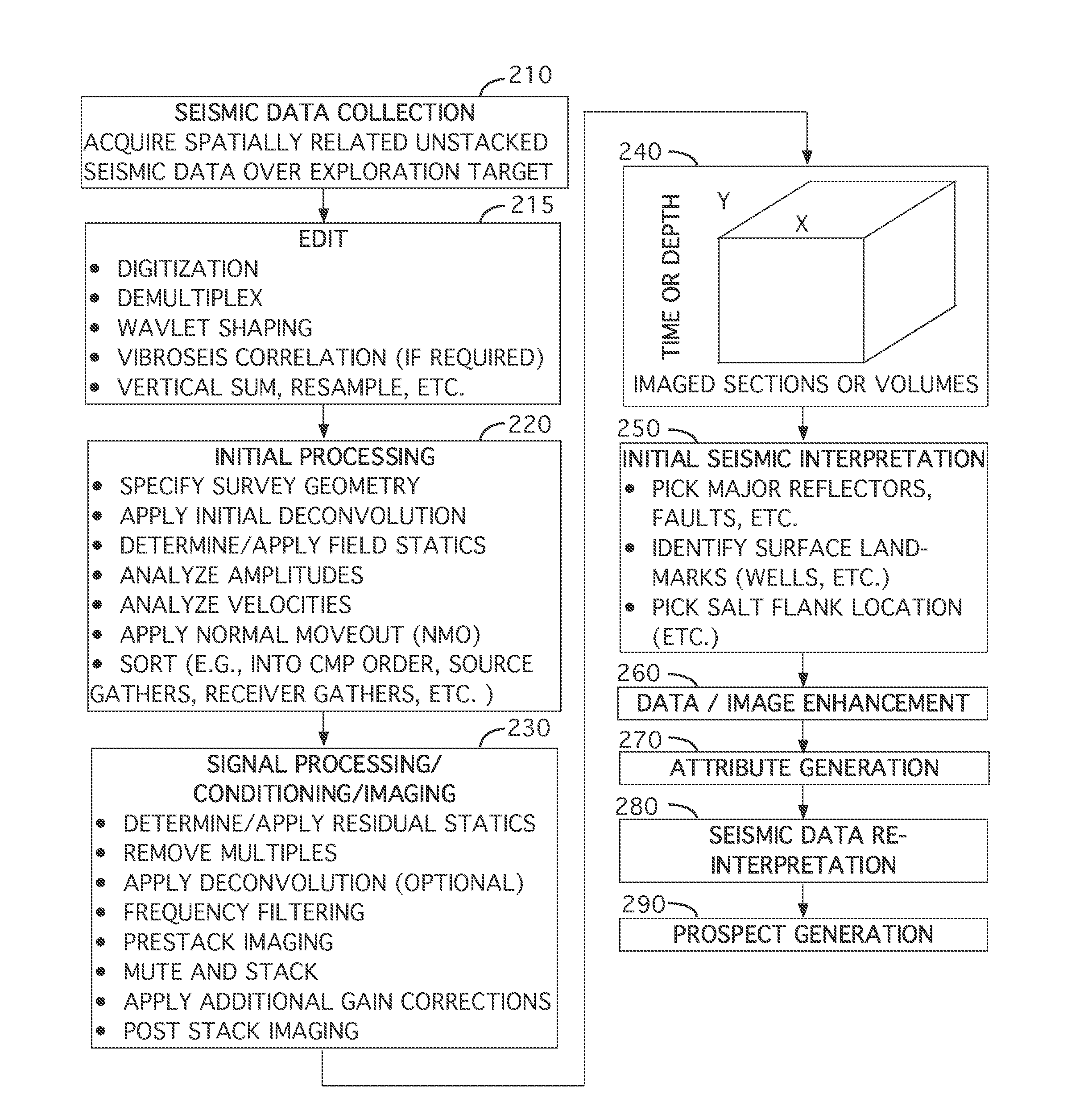
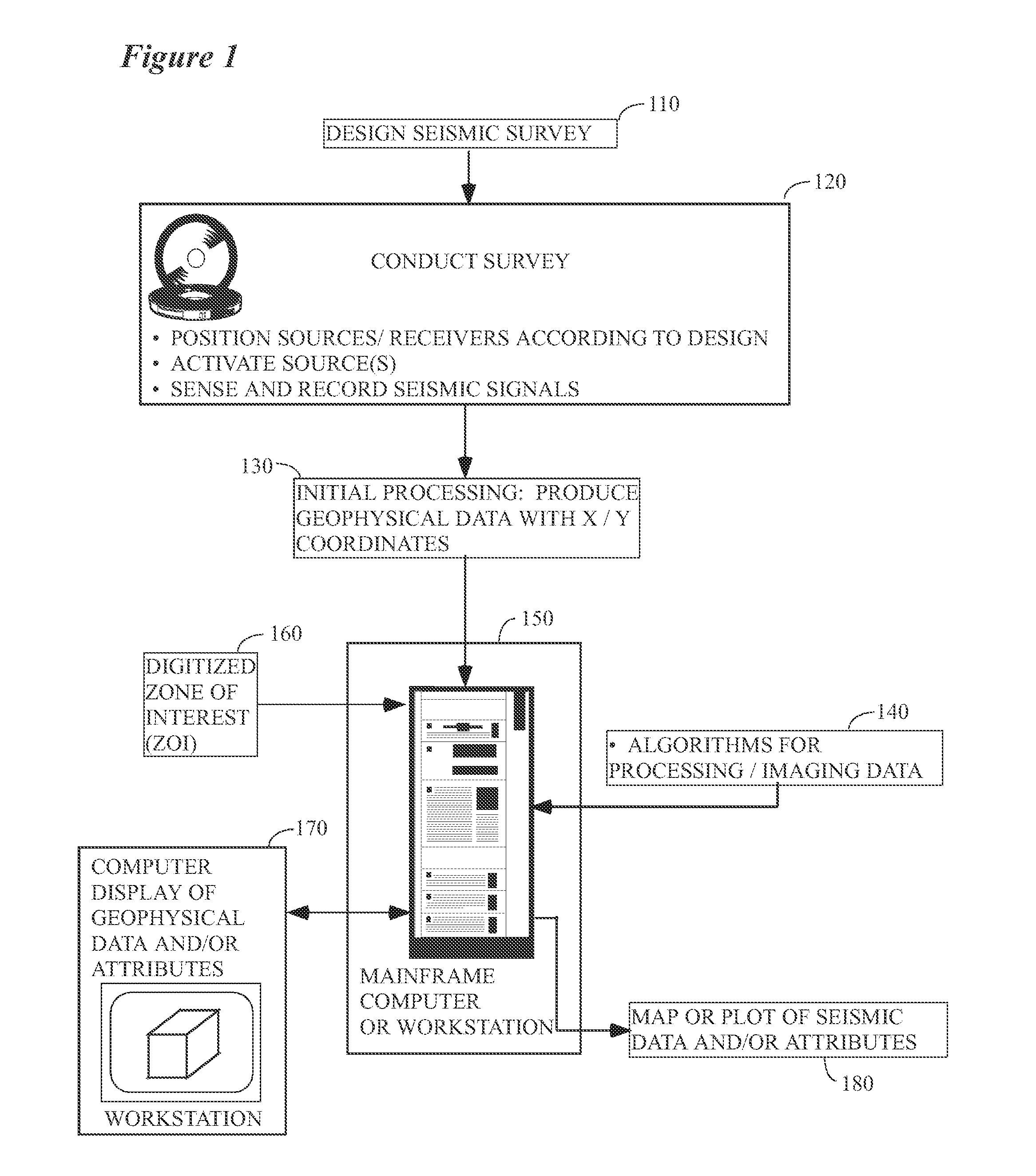
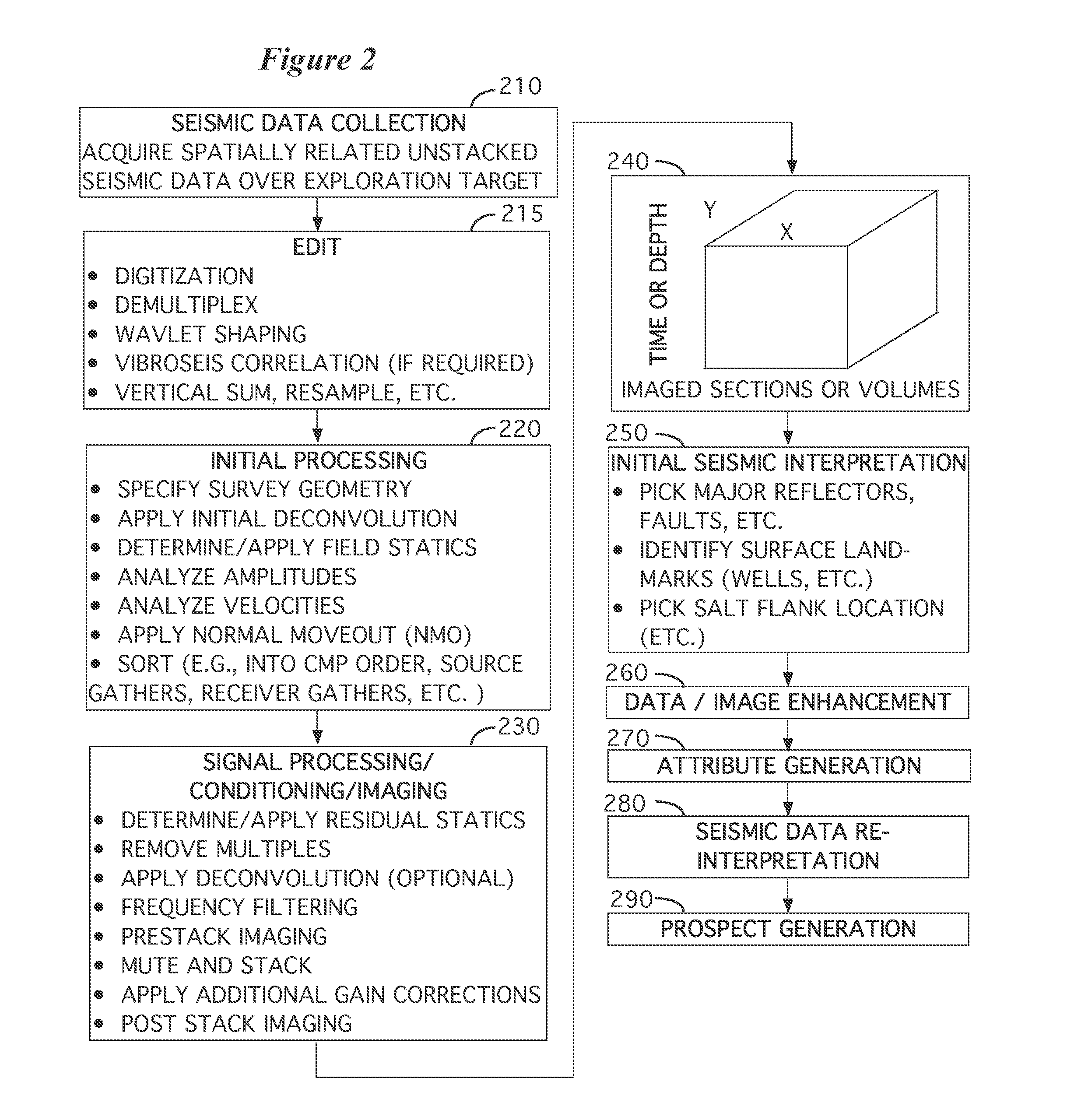
[0029]FIG. 1 illustrates the general environment in which the instant invention would typically be used. A seismic survey is designed 110 by the explorationist to cover an area of economic interest. Field acquisition parameters (e.g., shot spacing, line spacing, fold, etc.) are typically selected in conjunction with this step, although it is common to modify the ideal design parameters slightly (or substantially) in the field to accommodate the realities of conducting the survey.

[0030]Seismic data are col...


PUM


Abstract

According to a preferred aspect of the instant invention, there is provided herein a system and method for extending zero-offset or stacked wave-equation illumination analysis into the angle-gather domain, where it becomes an appropriate tool for assessing the effects of complex overburden on AVA response. A preferred method for doing this involves first creating an angle gather that has a perfect AVA response (i.e. a constant amplitude as a function of angle). This gather is then preferably used as a reflectivity map that is fed into a demigration process which creates modeled data that by construction carries with it a completely flat reflectivity signature. Remigration of such a data set then results in a gather on which any amplitude variation is more likely to be a measure of illumination effects alone. The resulting AVA signature on the gather can then be used to assess the validity of the AVA response on modeled or actual data, resulting in a useful AVA risk analysis.

Description

RELATED CASE[0001]This application claims the benefit of U.S. Provisional Patent Application Ser. No. 61 / 248,222 filed on Oct. 2, 2009, and incorporates said provisional application by reference into this disclosure as if fully set out at this point.TECHNICAL FIELD[0002]This invention relates to the general subject of seismic exploration and, in particular, to methods for estimating seismic and other signals that are representative of the subsurface in areas of complex subsurface structure.BACKGROUND OF THE INVENTION[0003]A seismic survey represents an attempt to image or map the subsurface of the earth by sending sound energy down into the ground and recording the “echoes” that return from the rock layers below. The source of the down-going sound energy might come, for example, from explosions or seismic vibrators on land, or air guns in marine environments. During a seismic survey, the energy source is placed at various locations near the surface of the earth above a geologic stru...

Claims


Application Information

Patent Timeline
IPC IPC(8): G01V1/30
CPCG01V2210/51G01V1/28
Inventor ALBERTIN, UWEASKIM, OLE JORANGHERASIM, MARIANA
Owner BP CORP NORTH AMERICA INC
Learn More