Optical Fiber Array Connectivity System for Multiple Transceivers and/or Multiple Trunk Cables

a technology of optical fiber array and trunk cable, which is applied in the field of fiber optic multi-strand cables, connectors, adapters, and patching systems, can solve the problems of inefficient use of trunk cables and complicating the connection schem

Active Publication Date: 2011-05-05
COMMSCOPE INC
View PDF12 Cites 42 Cited by
  • Summary
  • Abstract
  • Description
  • Claims
  • Application Information

AI Technical Summary

Benefits of technology

The foregoing is illustrative of the present invention and is not to be construed as limiting thereof. Although exemplary embodiments of this invention have been described, those skilled in the art will readily appreciate that many modifications are possible in the exemplary embodiments without materially departing from the novel teachings and advantages of this invention. Accordingly, all such modifications are intended to be included within the scope of this invention as defined in the claims. The invention is defined by the following claims, with equivalents of the claims to be included therein.

Problems solved by technology

Thus, the devices would occupy only eight of the 12 fibers of a 12-fiber trunk cable, which would result in inefficient use of the trunk cable.
However, adding more transceivers onto the trunk cable in order to utilize all of the trunk cable fibers may complicate the connection scheme.

Method used


Image

  • Optical Fiber Array Connectivity System for Multiple Transceivers and/or Multiple Trunk Cables
  • Optical Fiber Array Connectivity System for Multiple Transceivers and/or Multiple Trunk Cables
  • Optical Fiber Array Connectivity System for Multiple Transceivers and/or Multiple Trunk Cables

Examples


Embodiment Construction

The present invention will now be described more fully hereinafter, in which preferred embodiments of the invention are shown. This invention may, however, be embodied in different forms and should not be construed as limited to the embodiments set forth herein. Rather, these embodiments are provided so that this disclosure will be thorough and complete, and will fully convey the scope of the invention to those skilled in the art. In the drawings, like numbers refer to like elements throughout, and the thickness of lines, layers and regions may be exaggerated for clarity.

Unless otherwise defined, all terms (including technical and scientific terms) used herein have the same meaning as commonly understood by one of ordinary skill in the art to which this invention belongs. It will be further understood that terms, such as those defined in commonly used dictionaries, should be interpreted as having a meaning that is consistent with their meaning in the context of the relevant art and ...


PUM


Abstract

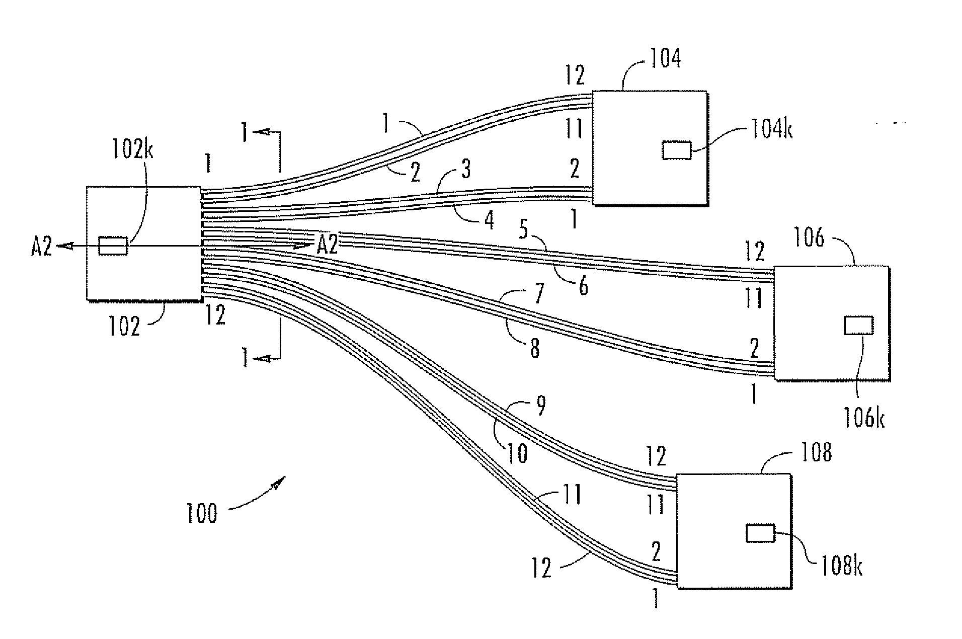
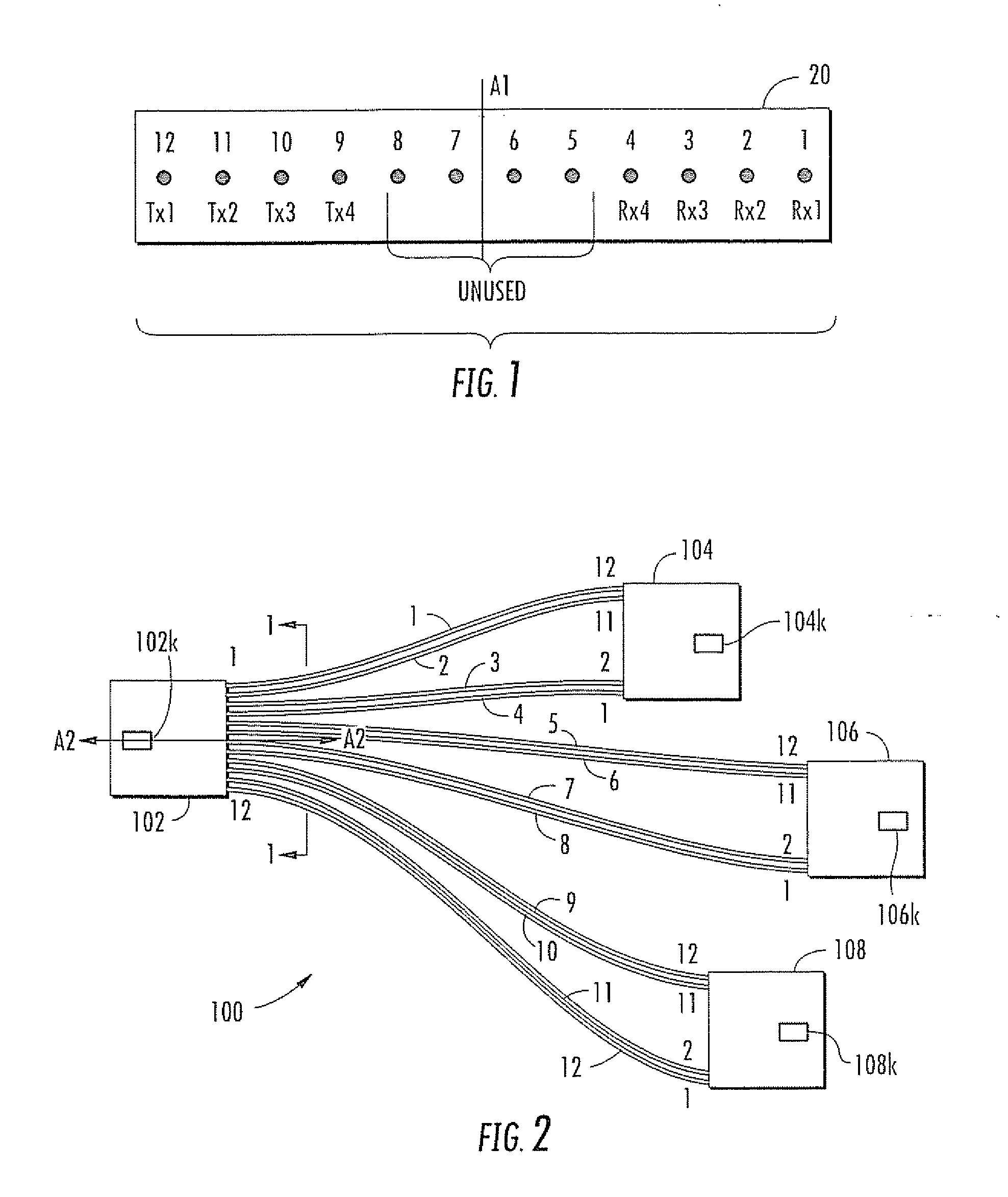
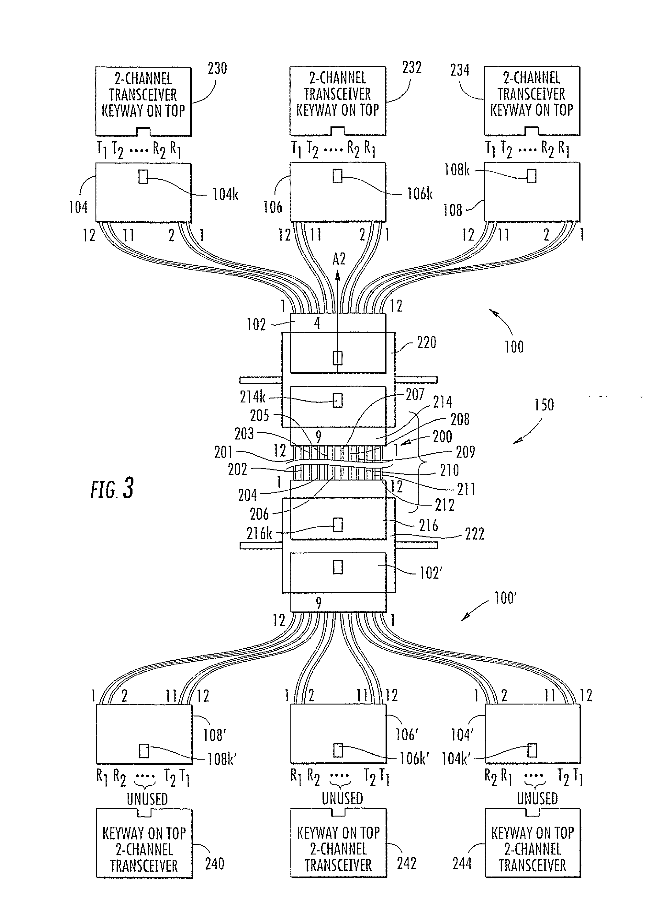
A transition device for an optical fiber connection system adapted to interconnect a trunk cable with a plurality of transceivers includes: a first set of at least four optical fibers, each of the optical fibers having a trunk end and a transceiver end; a single trunk end terminal having a plurality of trunk ports arranged in a first row, each port connected with a respective one of the set of optical fibers at its trunk end, wherein a first axis of symmetry divides the ports; and a plurality of transceiver end terminals, each of the transceiver end terminals having even numbers of transceiver ports, each of the transceiver ports receiving a respective one of the set of optical fibers at their transceiver ends. The arrangement of fibers received by each transceiver end terminal meet either of the following two conditions: (a) a first fiber originates from a first port in the trunk end terminal, and a second fiber originates from a second port in the trunk end terminal that is positioned at the mirror image location of the first port about the first axis of symmetry; or (b) each fiber is received in a first transceiver end terminal that has a corresponding second transceiver end terminal with the same number and arrangement of transceiver ports, and each fiber received in the first transceiver end terminal originates from a port in the trunk end terminal that has a mirror image port about the first axis of symmetry from which a fiber that is received in the second transceiver end terminal originates.

Description

FIELD OF THE INVENTION The present invention is directed generally to fiber optic multi-strand cables, connectors, adapters, and patching systems.BACKGROUND OF THE INVENTIONOptical fibers, both multi-mode and single mode, are commonly used for the transmission of signals of all sorts, including communication and data signals. Communications systems often transmit signals between transceivers (i.e., devices that can both transmit and receive optical signals) via different fibers in each direction. More specifically, one or more fibers will transmit signals from the first transceiver to the second, and one or more of the other fibers will transmit signals from the second transceiver to the first. In this manner, optical signals are not traveling along the same fiber in different directions.This arrangement would be fairly simple to organize for two transceiver devices that are permanently optically connected, but in practice transceivers are typically connected through a much larger n...

Claims


Application Information

Patent Timeline
Patent Type & Authority Applications(United States)
IPC IPC(8): H04B10/12G02B6/28
CPCG02B6/3608G02B6/28G02B6/4472
Inventor KOLESAR, PAUL
Owner COMMSCOPE INC
Why Eureka
Try Eureka