Shoulder prosthesis adjustable humeral head mechanism

a technology of shoulder prosthesis and humeral head, which is applied in the field of shoulder prosthesis, can solve the problems of compromising fixation, affecting the fixation effect, and not allowing surgeons to easily alter biomechanics,

Inactive Publication Date: 2011-05-05
DEPUY PROD INC
View PDF18 Cites 24 Cited by
  • Summary
  • Abstract
  • Description
  • Claims
  • Application Information

AI Technical Summary

Benefits of technology

[0015]According to yet another embodiment, a method of assembling a shoulder prosthesis for use in shoulder arthroplasty is provided. The method includes using a head having a cavity defined therein and a stem having a recess defined therein. A first connector having a proximal end and a distal end is also used. The first connector also includes a threaded cavity and an outer wall, the outer wall for engaging the recess of the stem. The threaded cavity opens at the proximal end of the first connector. The method also includes using a...

Problems solved by technology

Even with respect to these two divergent manners of surgical strategy, a common problem in shoulder surgery is matching the humeral resection angle to the predetermined angle designed into the prosthesis.
This strategy does not allow the surgeon to easily alter biomechanics after the prosthesis has been trialed, much less implanted.
This system, however, has two primary weaknesses.
First, the use of modular blocks obviously forces the design to only allow angular adjustments in finite increments.
Second, the need to adjust the angle through modular blocks forces the surgeon to remove the stem, change out a compo...

Method used


Image

  • Shoulder prosthesis adjustable humeral head mechanism
  • Shoulder prosthesis adjustable humeral head mechanism
  • Shoulder prosthesis adjustable humeral head mechanism

Examples


Embodiment Construction

)

[0028]While the invention is susceptible to various modifications and alternative forms, specific embodiments thereof have been shown by way of example in the drawings and will herein by described in detail. It should be understood, however, that there is no intent to limit the invention to the particular forms disclosed, but on the contrary, the intention is to cover all modifications, equivalents, and alternatives falling within the spirit and scope of the invention.

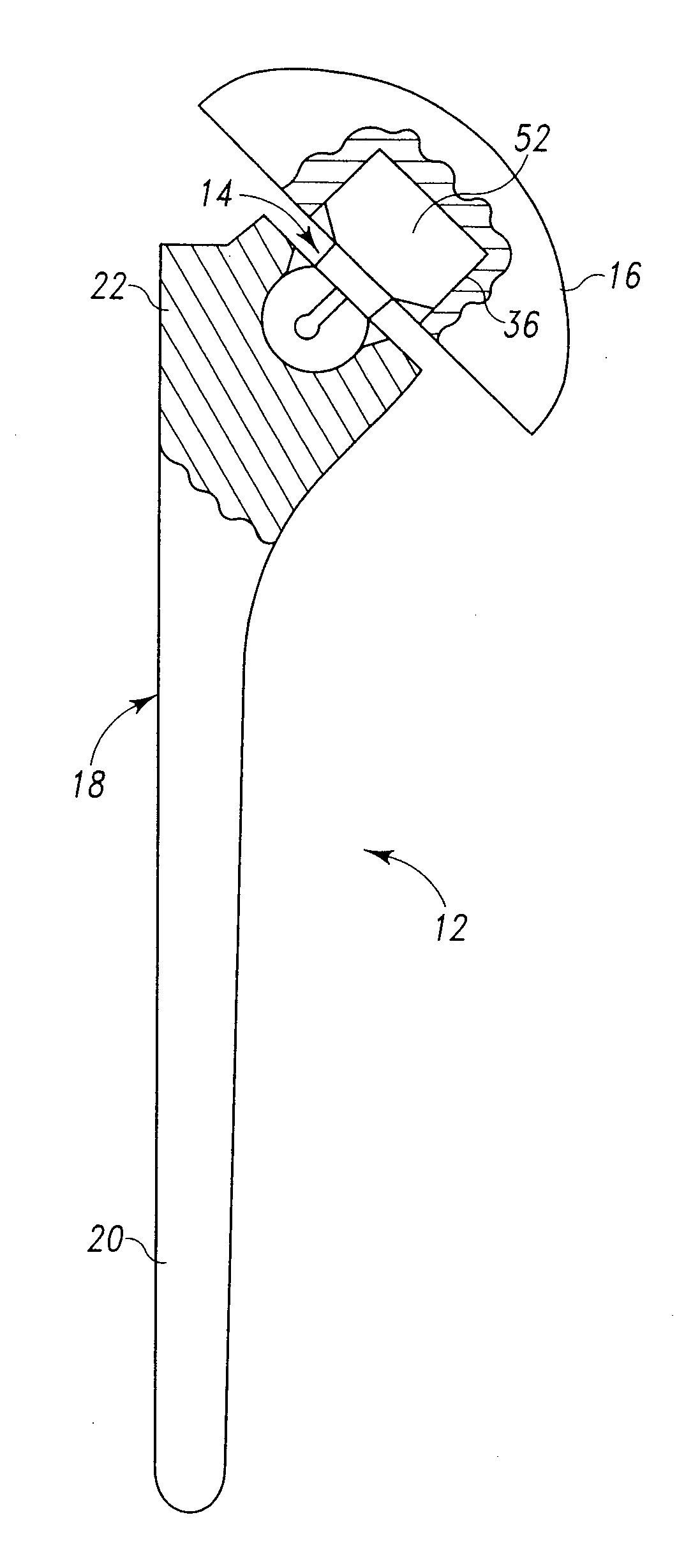
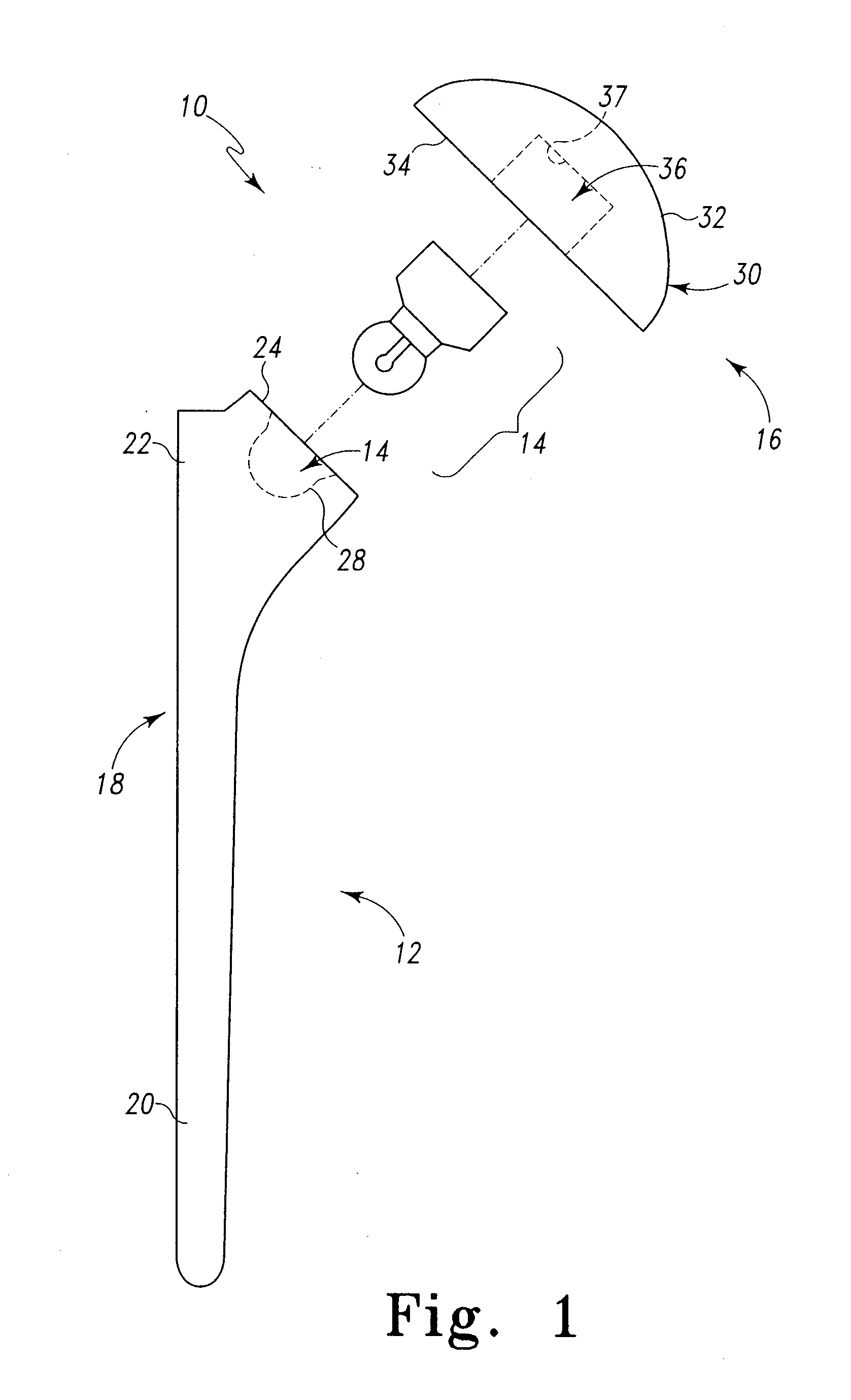
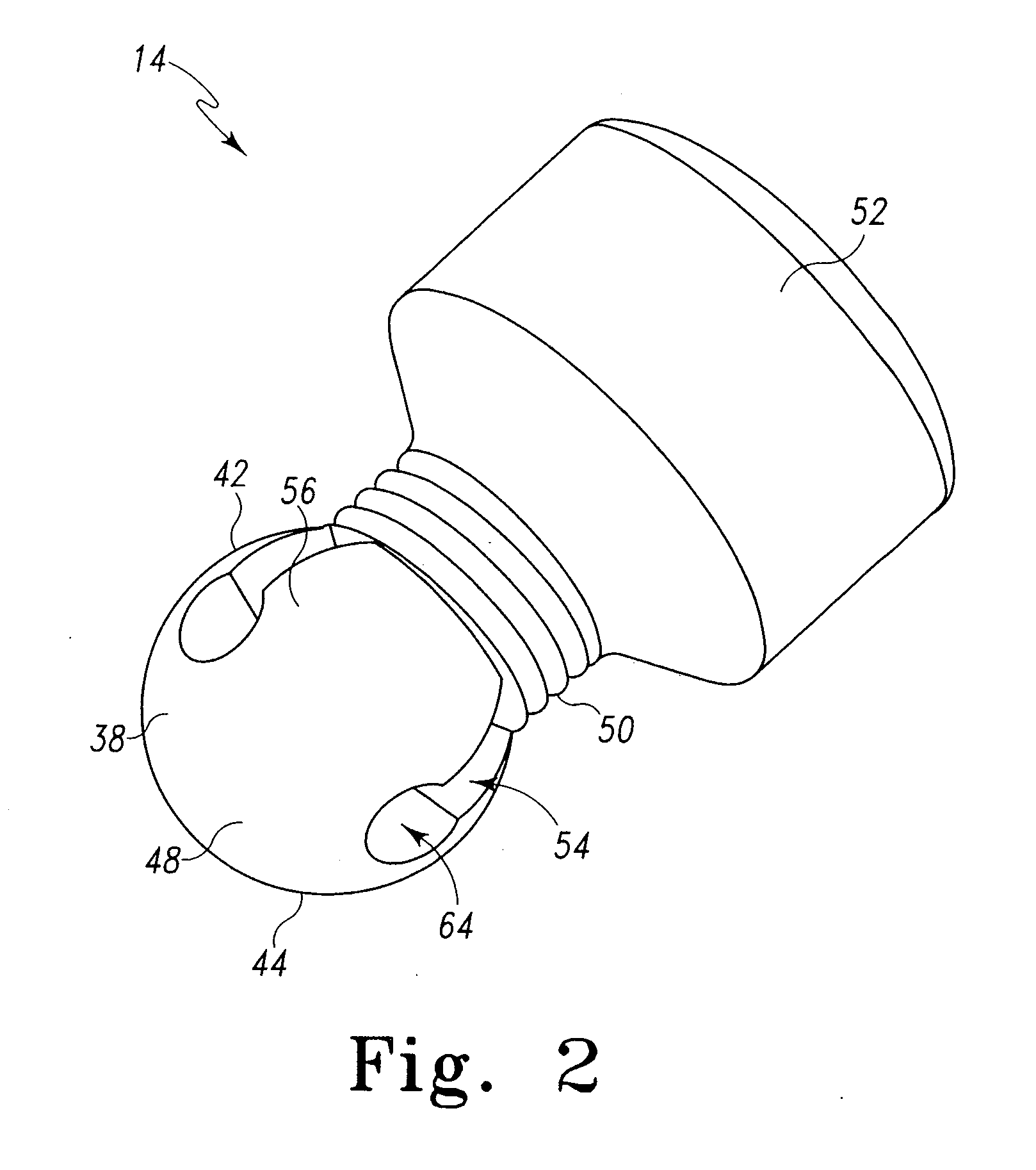
[0029]Referring now to FIG. 1 there is shown an exemplary embodiment of a shoulder prosthesis, generally designated 10. The shoulder prosthesis 10 includes a humeral component or stem 12, a neck 14, and a head 16. The head 16 is adapted to be coupled to the neck 14.

[0030]As depicted in FIG. 1, the stem 12 includes a body 18 having a distal or stem portion 20 and a proximal or neck portion 22. The stem 12 may or may not have fins, collars, suture holes or the like. The proximal portion 22 has a preferably substantially...


PUM

PropertyMeasurementUnit
Angleaaaaaaaaaa

Abstract

A shoulder prosthesis. The shoulder prosthesis includes a head having a cavity. The head further includes a first bearing surface configured to mate with a second bearing surface of a glenoid. The shoulder prosthesis also includes a stem having a recess defined therein, and the stem configured to be received by a humerus. The shoulder also includes a first connector having a proximal end and a distal end. The first connector also includes a threaded cavity and an outer wall. The outer wall engages the recess of the stem, and the threaded cavity opens at the proximal end of the first connector. A second connector having a threaded end sized and shaped to fit in the threaded cavity of the first connector is also included. The second connector also has a head connector end that is sized and shaped to fit within the cavity of the head. The outer wall of the first connector is sized and shaped to expand at the proximal end as the second connector is threaded into the threaded cavity.

Description

FIELD OF THE INVENTION[0001]The present invention relates to prosthetic devices particularly shoulder prostheses and, more particularly, to a shoulder prosthesis and method of use for shoulder replacement.BACKGROUND INFORMATION[0002]The state of the prosthetic shoulder market has progressed such that a surgeon generally approaches shoulder replacement surgery in one of two strategic ways. One strategic manner is to perform the shoulder replacement surgery in accordance with a manufacturer's shoulder prosthesis or shoulder prosthesis product line. Particularly, a surgeon is provided with instrumentation and technique guidelines for the particular shoulder prosthesis or prosthesis line. The guidelines and / or instrumentation direct or dictate the angle of humeral head resection for the implant (prosthesis). This angle is in relation to the humeral intramedullary (IM) canal and is designed to match an optimum set of angles already present in the prosthetic design.[0003]Another strategic...

Claims


Application Information

Patent Timeline
IPC IPC(8): A61F2/40B23P19/00
CPCA61F2/4014A61F2/4684A61F2002/30332A61F2002/30378A61F2002/30408A61F2002/30484Y10T29/53A61F2002/30616A61F2002/4037A61F2002/4044A61F2220/0025A61F2220/0033A61F2250/0006A61F2002/30538
Inventor GRANT, STUART R.
Owner DEPUY PROD INC
Why Eureka
Try Eureka