Post-mix dispenser assembly

a dispenser and post-mix technology, applied in the direction of liquid dispensing, liquid transfer devices, packaging, etc., can solve the problems of limited shelf life of pre-mixed beverages and the need for fresh pre-mixed beverages, and achieve the effect of convenient and convenient hookup and easy emptying

Inactive Publication Date: 2011-05-12
SCHROEDER INDS L L C
View PDF69 Cites 13 Cited by
  • Summary
  • Abstract
  • Description
  • Claims
  • Application Information

AI Technical Summary

Benefits of technology

[0014]It is an object of the invention to provide, in one embodiment of a manually operated non-electric post-mix valve, a manually operated post-mix “T” valve in which the upstream pressurized fluid therein will urge a normally closed, seated piston or stem into the seated fluid flow blocking position, which normally closed seated position prevents the flow of pressurized fluid therethrough.
[0017]It is a further object of the present invention to provide for a nozzle assembly which can provide for more complete mixing of a first and second fluid on the inside walls of a nozzle housing.SUMMARY OF THE INVENTION
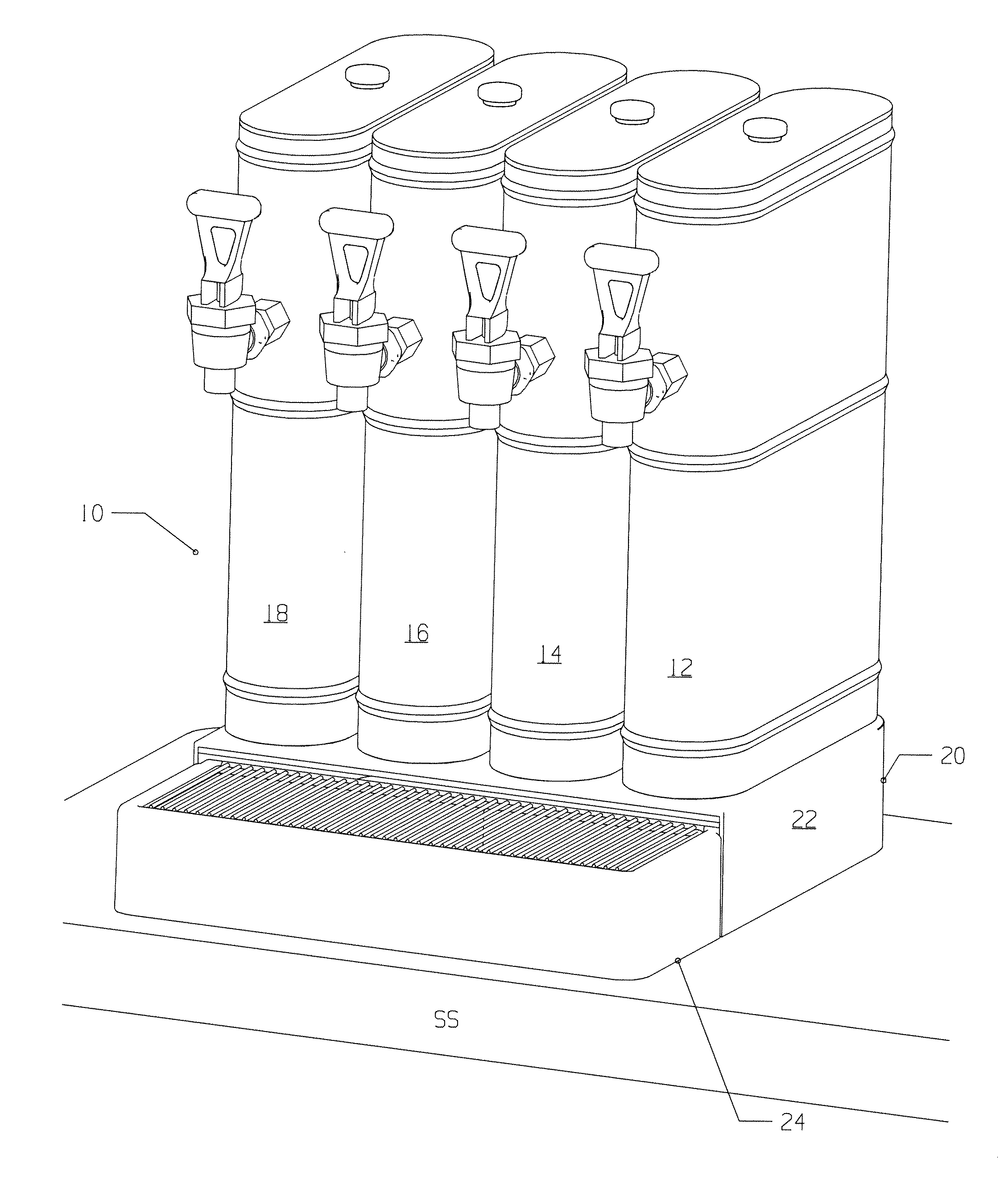
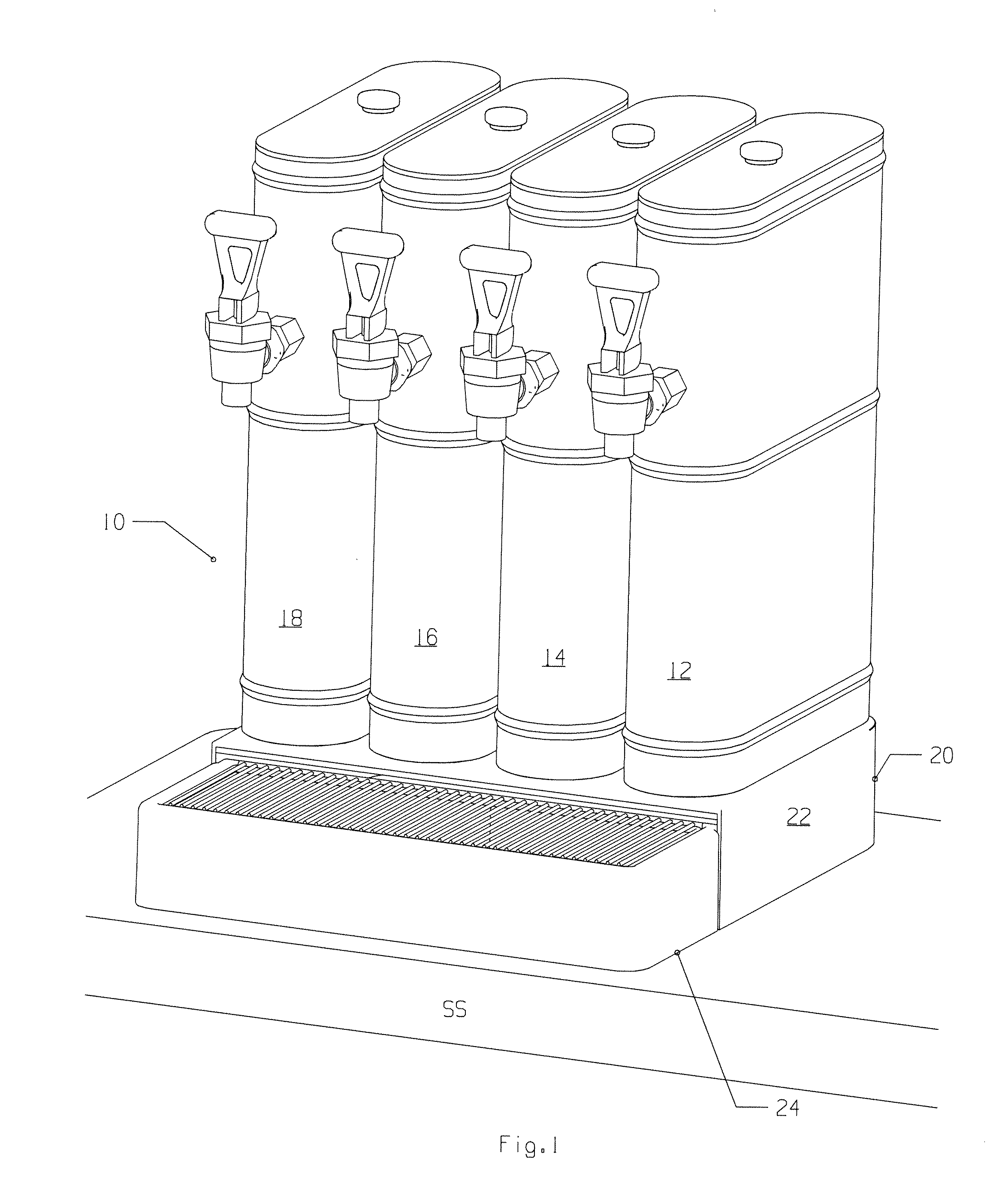
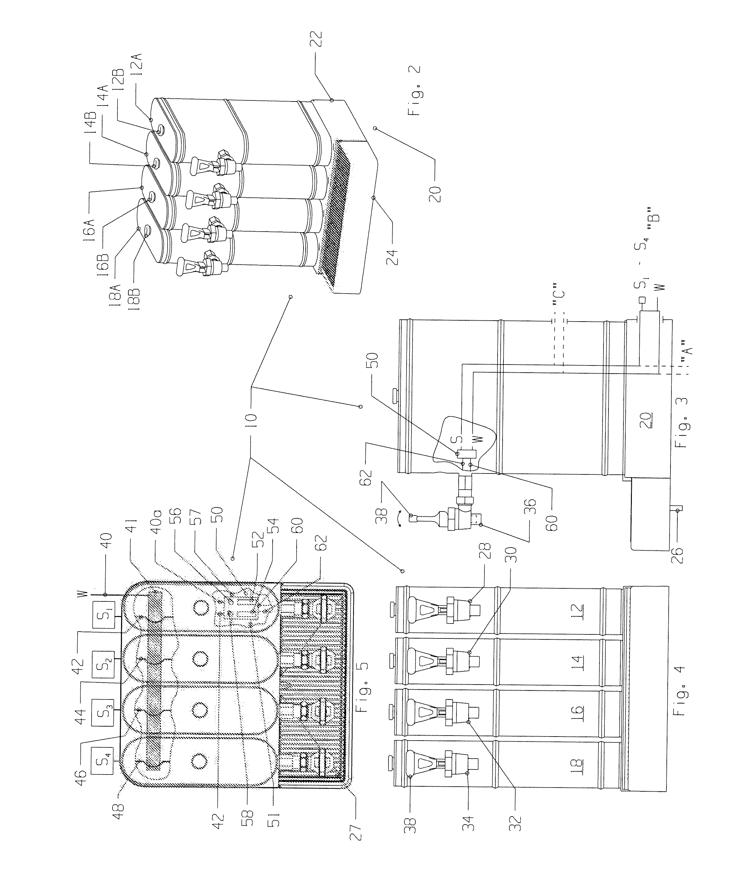
[0022]Applicant's urn assembly may include a base having a drip tray removable therefrom for easy emptying, which drip tray typically includes a cutout removable therefrom to allow easy and convenient hookup to a drain line.

Problems solved by technology

However, pre-mixed beverages have a limited shelf-life.
While the customer prefers, generally, pre-mixed beverages, those pre-mixed beverages must be fresh due to their limited shelf life.
Further, post-mix valves known in the art typically do not mix a first and second fluid in the nozzle from a “T” valve.

Method used


Image

  • Post-mix dispenser assembly
  • Post-mix dispenser assembly
  • Post-mix dispenser assembly

Examples


first embodiment

[0082]Turning to fluid flow (and with reference to FIGS. 10C, 10E, 10F, and 10G) from first and second fluid lines 120 / 122 to nozzle assembly 118, reference is made to the following. Each chamber seat 178 is fluidly coupled to a crossover channel 182 and each crossover channel is coupled to a down flow channel 184. Down flow channels 184 terminate at lower base 198, which is sealed to body 168 and provides through channels 198A and 198B (each an extension of a flow channel) for passage of first and second fluid into channels 158A and 158B (each an extension of 198A and 198B, respectively). Flow through the diffuser nozzle assembly 118 is then the same as set forth in the

[0083]Turning back to lower base 198, it is seen to have retainer seats 1100 for the receipt of retainers 194 therein. O-rings 1102 are captured by sealing retainers 194 into lower base 198 by slide fit into retainer seats 1100. Retainers 194 therefore are seen to retain O-rings, provide retainment for the lower end ...

third embodiment

[0087]Series III, FIGS. 12A-12I, illustrate Applicants' manually operated post-mix dispensing valve which may be used with urns or other dispensing devices. Like the earlier embodiments, it is generally T-shaped and may be referred to as a post-mix T-valve.

[0088]Typically the dispensing valve is set so that a product delivery assembly 2112 is horizontally mounted to the urn or urns, in this regard, similar to the earlier embodiments of the valve. The horizontal longitudinal axis B of the product delivery assembly 2112 engages main body 2114, which typically has a vertical longitudinal axis A when engaged with an urn (see for example, FIG. 11).

[0089]Extending generally upward from main body 2114 is valve assembly 2116, including a handle 2142 for manually operating the post-mix assembly and dispensing fluid therefrom. Extending generally below and on a vertical axis to the main body 2114 is diffuser nozzle assembly 2118.

[0090]Product delivery assembly 2112 delivers the first and seco...


PUM


Abstract

A beverage dispensing assembly which has one or more urns to which a manual, post-mix valve is engaged, on front walls thereof. The urn or urns do not contain fluid, rather, at least, a pair of fluid lines carrying pressurized fluid to the post-mix valve, which may be a “T” valve. The two fluid lines carry fluid from a first and a second fluid source, typically pressurized, which sources are remote from the urn or urns. The urns have walls defining an interior volume. The interior volume is adapted to receive lines carrying a pressurized concentrate and a pressurized base fluid, such as water. The lines are adapted to be contained at least partly within the inner volume of the urn or urns of the urn assembly and engage a near end of the post-mix “T” valve where the post-mix “T” valve engages the front wall of the urn. If the assembly is comprised of more than one urn, it may include a base, designed to hold the urns in side-by-side alignment.

Description

[0001]This application claims the benefit of, incorporates by reference, and priority from: U.S. Provisional Patent Application Ser. No. 61 / 260,097, filed Nov. 11, 2009; and U.S. patent application Ser. No. 12 / 693,916, filed Jan. 26, 2010.FIELD OF THE INVENTION[0002]Valve and dispenser assemblies, more specifically, a post-mix dispenser assembly comprising one or a multiple substantially identical urn assemblies and valves, namely, post-mix valves.BACKGROUND OF THE INVENTION[0003]This application incorporates by reference the following: U.S. patent application Ser. No. 12 / 286,441, filed Sep. 30, 2008, published Apr. 2, 2009; and U.S. patent application Ser. No. 12 / 465,283, filed May 13, 2009, published Nov. 19, 2009.[0004]Psychologically, most customers for dispensed beverages prefer their beverage “fresh brewed.” For example, most consumers prefer fresh brewed tea, rather than tea that is mixed upon dispensing. That is to say, tea that is mixed upon dispensing (concentrate and wate...

Claims


Application Information

Patent Timeline
Patent Type & Authority Applications(United States)
IPC IPC(8): A23L2/00B67D7/06
CPCB67D1/0021B67D1/0082B67D1/0048B67D1/0044B67D1/06B67D1/0872B67D7/74
Inventor SANTY, DAVIDSCHROEDER, A.A. "JUD"ABSALON, DEBORAH
Owner SCHROEDER INDS L L C
Why Eureka
Try Eureka