Microwave heating apparatus

Active Publication Date: 2011-05-12
PANASONIC CORP
View PDF6 Cites 41 Cited by
  • Summary
  • Abstract
  • Description
  • Claims
  • Application Information

AI Technical Summary

Benefits of technology

[0028]With the microwave heating apparatus of the present invention, the microwave supplied to the heating chamber can be substanti

Problems solved by technology

A semiconductor element has lower thermal durability in comparison to the magnetron

Method used


Image

  • Microwave heating apparatus
  • Microwave heating apparatus
  • Microwave heating apparatus

Examples


first embodiment

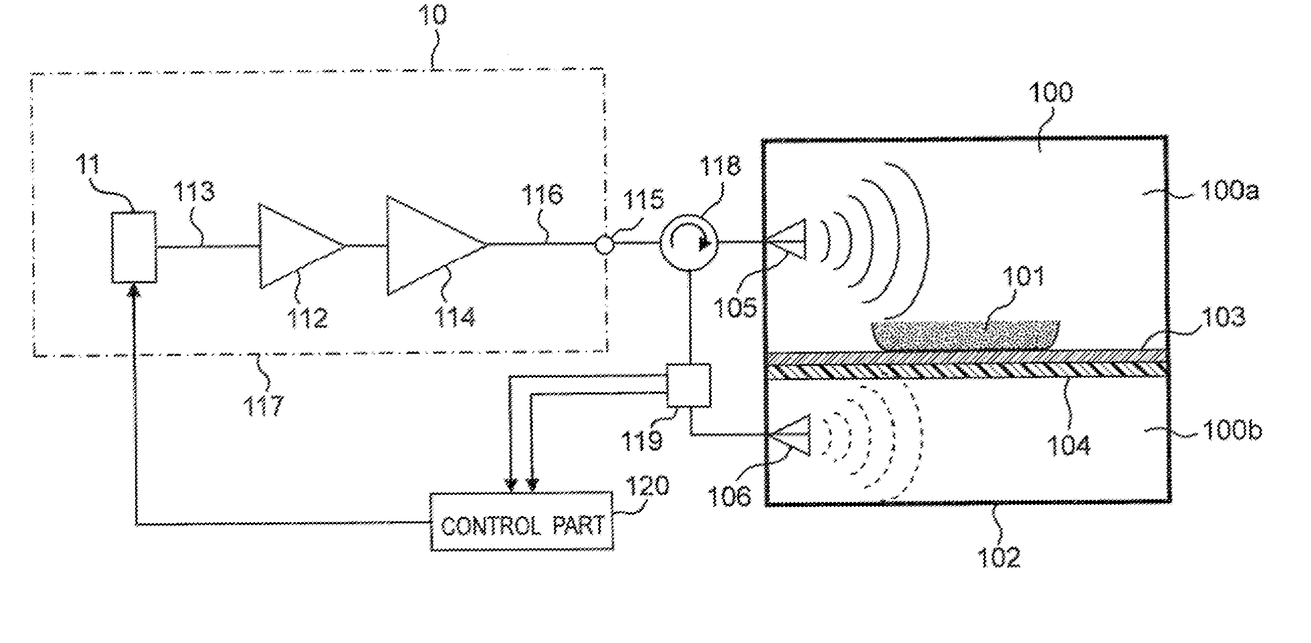
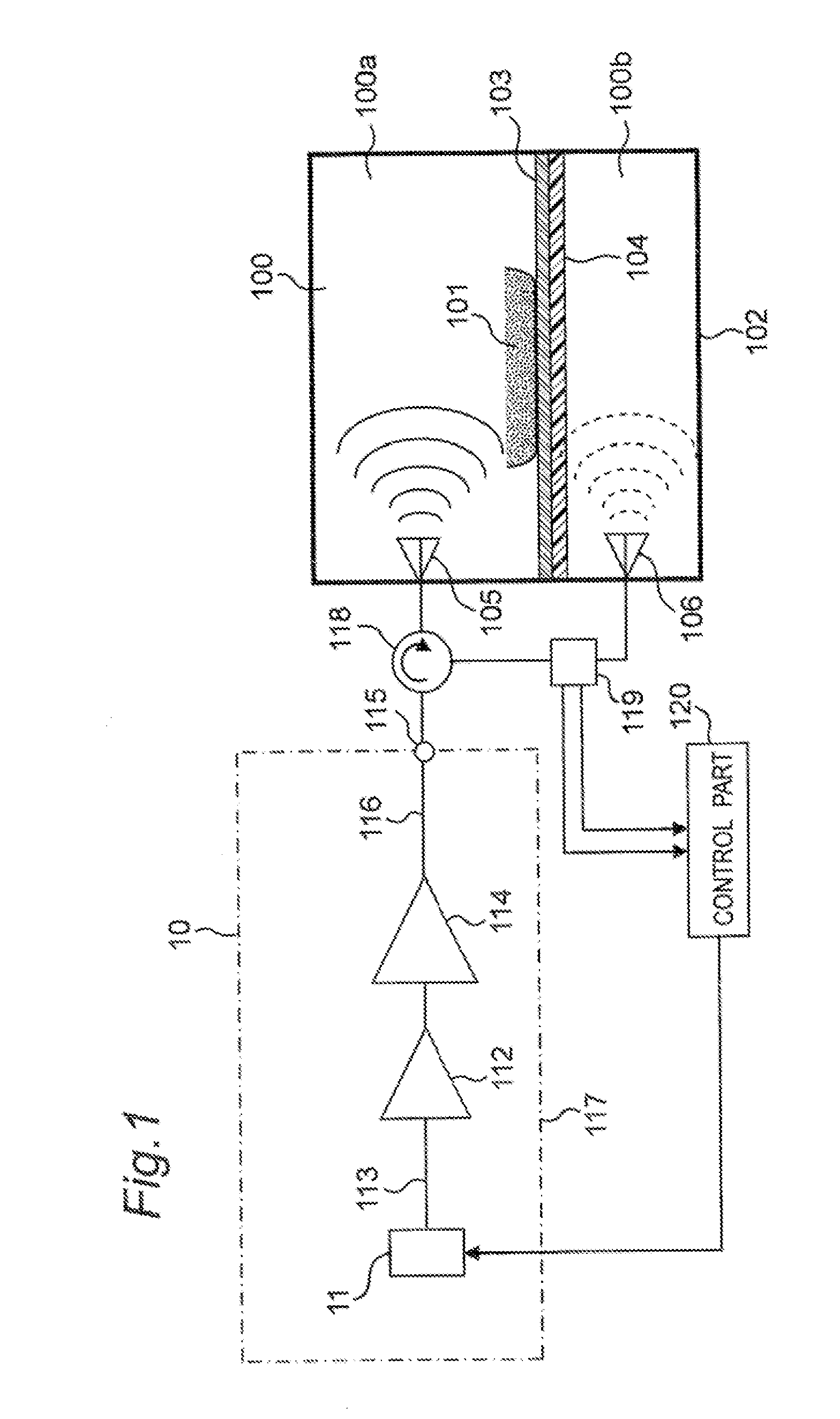
[0053]FIG. 1 is a block diagram showing a configuration of a microwave heating apparatus of a first embodiment according to the present invention.

[0054]As shown in FIG. 1, in the microwave heating apparatus of the first embodiment, a microwave generation part 10 is provided with a microwave oscillation part 11 for generating a microwave, a plurality of steps of microwave amplification parts 112, 114 for amplifying an output of the microwave oscillation part 11, a microwave transmission passage 113 for guiding the output of the microwave oscillation part 11 to the former microwave amplification part 112, and a microwave transmission passage 116 for guiding an output of the main microwave amplification part 114 at a latter stage to an output part 115 of the microwave generation part 10. The microwave oscillation part 11 and the microwave amplification parts 112, 114 are formed with using semiconductor elements. As described above, in the microwave generation part 10, the microwave fro...

second embodiment

[0116]Hereinafter, a microwave heating apparatus of a second embodiment according to the present invention will be described with reference to attached FIGS. 6 to 10. FIG. 6 is a block diagram showing a configuration of the microwave heating apparatus of the second embodiment. FIG. 7 is a frequency characteristic diagram of the microwave heating apparatus of the second embodiment. FIGS. 8 to 10 are flowcharts showing actions in the microwave heating apparatus of the second embodiment. In the description of the second embodiment, constituent elements having the same functions and configurations as those of the above first embodiment will be given the same symbols, and the description of the first embodiment will be applied to description thereof.

[0117]In FIG. 6, the microwave generation part 10 in the microwave heating apparatus of the second embodiment has the microwave oscillation part 11 formed with using the semiconductor element, a power divider 212 for dividing the output of th...

third embodiment

[0174]Hereinafter, a microwave heating apparatus of a third embodiment according to the present invention will be described with reference to attached FIGS. 11 to 15. FIG. 11 is a block diagram showing a configuration of the microwave heating apparatus of the third embodiment. FIG. 12 is a frequency characteristic diagram of the microwave heating apparatus of the third embodiment. FIGS. 13 to 15 are flowcharts showing actions in the microwave heating apparatus of the third embodiment. In the description of the third embodiment, the constituent elements having the same functions and configurations as those of the above first embodiment will be given the same symbols, and the description of the first embodiment will be applied to description thereof.

[0175]In FIG. 11, the microwave heating apparatus of the third embodiment has two microwave generation parts 10a, 10b. The first microwave generation part 10a has a microwave oscillation part 311 formed with using a semiconductor element, ...


PUM


Abstract

A microwave heating apparatus includes a microwave generation part 10 using a semiconductor element, and first and second heating chambers 100a, 100b to each of which a microwave generated in the microwave generation part is fed. A reflected microwave returned from at least one of the first and second heating chambers 100a, 100b to the microwave generation part is transmitted to the other heating chamber by a circulation type non-reciprocal circuit 118, so that generated power of the microwave generation part is substantially completely consumed upon heating of an article to be heated.

Description

TECHNICAL FIELD[0001]The present invention relates to a microwave heating apparatus provided with a microwave generation part that is configured by using a semiconductor element.BACKGROUND ART[0002]A conventional microwave heating apparatus provided with a microwave generation part is configured by using a vacuum tube called as a magnetron for the microwave generation part in general as represented by a microwave oven.[0003]A semiconductor element has lower thermal durability in comparison to the magnetron, and thus there is a fear that the element is destructed when exposed to high heat. In case that the microwave generation part formed with using the semiconductor element is developed to the microwave heating apparatus, a circulator forming a circulation type non-reciprocal circuit is used so that high-frequency power amplified in the microwave generation part is supplied to a heating chamber and the high-frequency power is not returned to the microwave generation part. This circu...

Claims


Application Information

Patent Timeline
IPC IPC(8): H05B6/68H05B6/64
CPCH05B6/6402H05B6/686H05B6/705H05B6/72H05B6/80Y02B40/143Y02B40/146H05B6/688H05B6/6494H05B2206/044Y02B40/00
Inventor NOBUE, TOMOTAKAYASUI, KENJIOOMORI, YOSHIHARUMIHARA, MAKOTO
Owner PANASONIC CORP
Why Eureka
Try Eureka