
Cable fastening device

Inactive Publication Date: 2011-05-12
ILLINOIS TOOL WORKS INC
View PDF50 Cites 9 Cited by
  • Summary
  • Abstract
  • Description
  • Claims
  • Application Information

AI Technical Summary

Benefits of technology

[0007]The cable fastening device according to the invention comprises a vibration attenuating material layer, which material layer is arranged in between the fastening surface and the connecting piece of the cable fastening device. This vibration attenuating material layer improves the grip of the cable fastening device on the fastening surface, and prevents, as an elastic material, the cable fastening device and particularly the connecting piece from being detached from the fastening surface. The vibration attenuating material layer is advantageously made of rubber.

Problems solved by technology

However, the majority of known solutions is not suitable to be used in demanding usage conditions, for example in the engine rooms of ships, where said fastening arrangements must reliably endure even remarkable vibrations.
In this way, a solid fastening arrangement is obtained, but its preparation is expensive and takes a long time, and it is not very easily modified.
The problem with this solution is that the fastening pieces are easily detached owing to vibration.

Method used


Image

  • Cable fastening device
  • Cable fastening device

Examples


Embodiment Construction

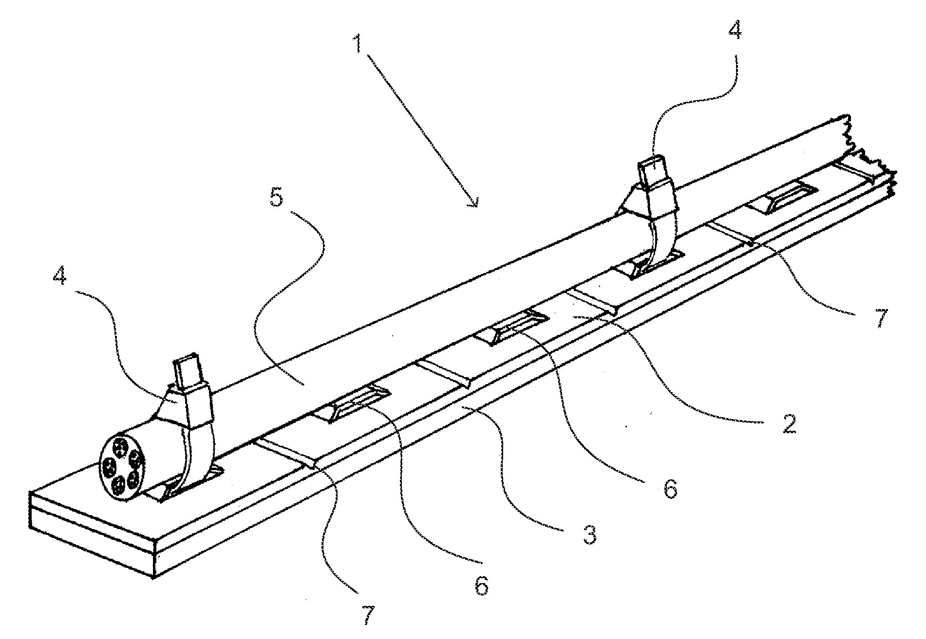
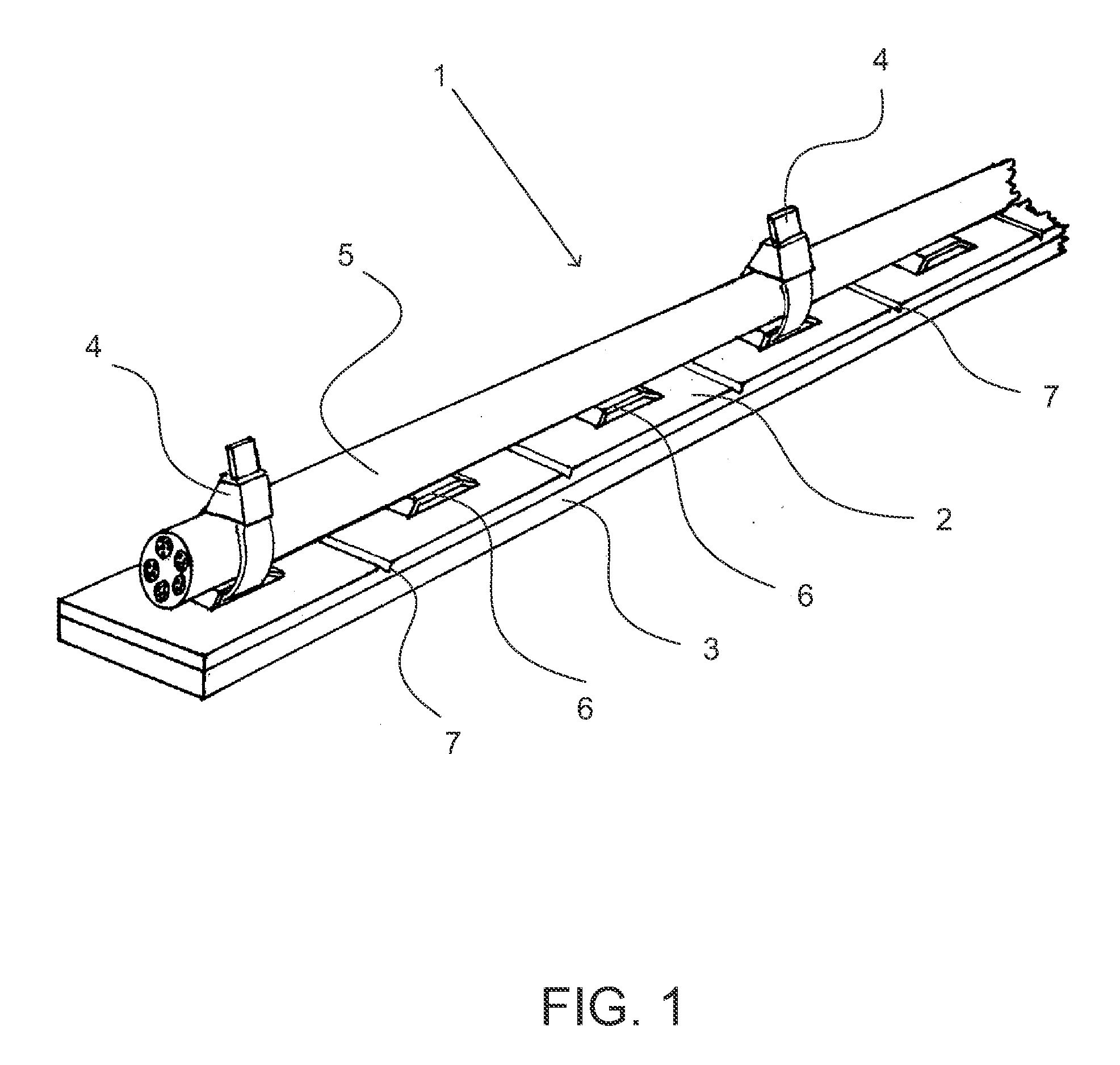
[0011]A cable fastening device 1 illustrated in FIG. 1 comprises a connecting piece 2, a vibration attenuating material layer 3, and cable ties 4 for fastening the cable 5 to the cable fastening device.

[0012]On the top surface of the connecting piece 2 of the cable fastening device 1, there are provided brackets or binding lugs 6 forming loops that are open on the sides, and through said loops the cable 5 can be attached to the cable fastening device by means of cable ties 4 in the way illustrated in the drawing. The connecting piece 2 is advantageously made of steel strip, in which case its design and particularly the binding lugs 6 can be realized for example by die cutting.

[0013]On the top surface of the connecting piece 2, there are advantageously made cutting grooves 7 in the area located in between the binding lugs 6, and said cutting grooves extend from one edge of the connecting piece 2 to the other edge thereof, in a direction that is transversal to the lengthwise direction...


PUM


Abstract

A cable fastening device comprising at least one connecting piece for fastening a cable to a fastening surface, and at least one binding lug protruding out of the outer surface of the connecting piece, by intermediation of which binding lug one or several cables are fastened to the fastening device, wherein the fastening device comprises a vibration attenuating material layer arranged in between the connecting piece and the fastening surface for the fastening device.

Description

BACKGROUND OF THE INVENTION[0001]The invention relates to a cable fastening device used for fastening cables, pipes etc. More particularly, the invention relates to a fastening device, by means of which cables, pipes etc. can be fastened to different surfaces, particularly in demanding usage environments.[0002]Several different solutions are known for fastening cables, wires, pipes etc. However, the majority of known solutions is not suitable to be used in demanding usage conditions, for example in the engine rooms of ships, where said fastening arrangements must reliably endure even remarkable vibrations.[0003]Generally the fastening of cables and the like in these demanding targets is realized so that first there are provided fastening lugs for the cables, for instance by welding separate lugs in place, whereafter the cables are fastened to said lugs. In this way, a solid fastening arrangement is obtained, but its preparation is expensive and takes a long time, and it is not very ...

Claims


Application Information

Patent Timeline
IPC IPC(8): F16L3/08F16F7/00
CPCF16L3/127H02G3/32F16L55/035F16G11/00F16L3/00F16L3/08F16L11/26F16L55/0336H02G3/00H02G3/26H02G3/266H02G3/30H02G7/125H02G7/14
Inventor KOMARO, RAIMO A.KOMARO, KIM
Owner ILLINOIS TOOL WORKS INC
Features
  • Generate Ideas
  • Intellectual Property
  • Life Sciences
  • Materials
  • Tech Scout
  • Unparalleled Data Quality
  • Higher Quality Content
  • 60% Fewer Hallucinations
Learn More