Display control device for remote control device

a remote control and display control technology, applied in control devices, instruments, vehicle components, etc., can solve the problems of user increasing the time it takes for users to gaze at the operation screen, and preventing users from losing the position of the cursor, so as to prevent users from losing the position, easy to recognize the position, and reliably guide users

Inactive Publication Date: 2011-05-12
DENSO CORP
View PDF9 Cites 19 Cited by
  • Summary
  • Abstract
  • Description
  • Claims
  • Application Information

AI Technical Summary

Benefits of technology

[0011]In view of the forgoing, it is an objective of the present invention to provide a display control device for a remote control device, the display control device being capable of preventing a user from losing position of an identification display mark even when the identification display mark, which indicates an icon in a selection state, is moved due to switch of display from one operation screen to another operation screen.
[0012]According to an aspect of the present invention, a display control device for a remote control device is provided. The display control device is configured to have connection with a display device and a remote control device. The display device is configured to display one operation screen selectively from among multiple operation screens for accepting an operation directed to a control target apparatus. The multiple operation screens include a first operation screen and a second operation screen on each of which a set of icons are arranged. The first operation screen and the second operation screen are different from each other in icon arrangement. The remote control device is spaced apart from the display device and is manipulatable by a user. The display control device is configured to perform display control in manners including the followings. The display control device receives an input of an instruction about an operation direction from the remote control device, performs processing according to the input, and causes the display device to display a, result of the processing on the displayed one operation screen according to the input. The display control device causes the display device to display an identification display mark on the displayed one operation screen, so that: the identification display mark indicates that one icon of the set of icons on the displayed one operation screen, the one icon being presently selected from among the set of icons, is in a selection state; and the identification display mark is displayed in association with the one icon selected on the displayed one operation screen. When display is switched from the first operation screen to the second operation screen, the display control device shifts the selection state from the one icon selected on the first operation screen to an initial selection icon pre-set on the second operation screen and causes the display device to display a visual effect indicative of a direction from position of the selected one icon to position of the initial selection icon.
[0013]According to the above display control device, when the position of the identification display mark (e.g., cursor) indicative of an icon in the selection state is largely moved due to the switch of display from the first operation screen to the second operation screen, the visual effect can reliably guide a user to a destination icon (i.e., the initial selection icon). Therefore, the display control device enables a user to easily recognize the position of the initial selection icon on the second operation screen, and improves operability of the remote control device. Moreover, unlike a pointer which is continuously displayed to continuously track or trace a result of a user's manipulation for inputting the instruction about the operation direction, the visual effect indicative of the direction to the initial selection icon on the second operation screen is displayed only when the display is switched from the first operation screen to the second operation screen. Therefore, it is possible to reduce a time for user to gaze the operation windows and a user's operation burden, as compared to the pointer. It should be noted that even when the pointer is displayed in a conventional manner, the use of the visual effect indicative of the direction to the initial selection icon can reduce a user's operation burden accordingly. Therefore, the present invention is applicable to both of a remote control system configured to display a pointer and a remote control system configured not to display a pointer.

Problems solved by technology

According to the above operation method however, it takes an effort and a time to move the pointer onto a desired position on the operation screen.
A period of time for a user to gaze the operation screen is increased, which may be troublesome.
However, when position of the cursor, which indicates an icon in the selection state, is largely moved due to the switch of the display from one operation screen to another operation screen, a user may lose the position of the cursor.

Method used


Image

  • Display control device for remote control device
  • Display control device for remote control device
  • Display control device for remote control device

Examples


Embodiment Construction

[0025]Embodiments of the present invention will be described below with reference to the accompanying drawings. In should be noted that embodiments of the present invention are not limited to the below-described embodiments. Embodiments of the present invention can have various forms.

[0026](Configuration of Remote Control System)

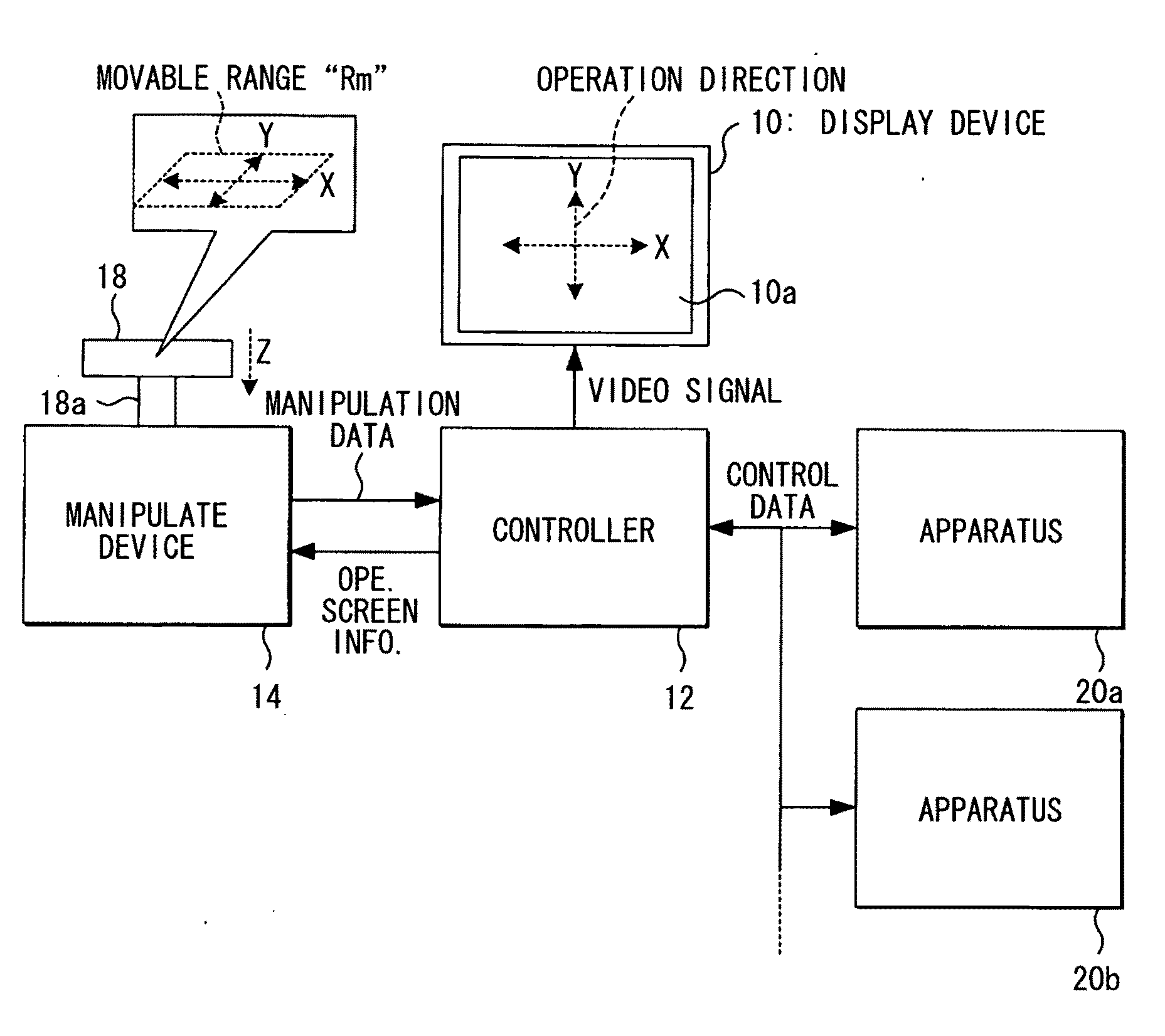
[0027]FIG. 1 is a block diagram schematically illustrating a remote control system according to one embodiment.

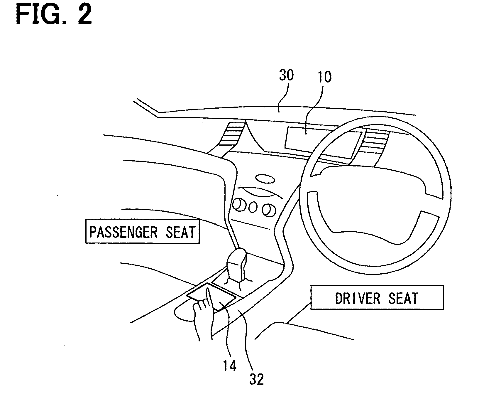
[0028]The remote control system can be used for operation on an apparatus mounted to, for example, a vehicle. As shown in FIG. 1, the remote control system includes a display device 10, a controller 12, a manipulation device 14, and an apparatus 20. The display device 10 includes a display panel 10a (e.g., a liquid crystal display panel) for displaying thereon an image. The controller 12 controls components of the remote control system. The manipulation device 14 is manipulatable by a user. The apparatus 20 is a control target apparatus, which may b...


PUM


Abstract

A display control device for a remote control device is disclosed. The display control device is configured to have connection with a display device and a remote control device spaced apart from each other. The display device is configured to display an operation screen having multiple icons for accepting an operation directed to a control target apparatus. When display is switched from a first operation screen to a second operation screen having a different icon arrangement, the display control means shifts an icon selection state from one icon selected on the first operation screen to an initial selection icon pre-set on the second operation screen and causes the display device to display a visual effect indicative of a direction from position of the selected one icon to position of the initial selection icon.

Description

CROSS REFERENCE TO RELATED APPLICATION[0001]The present application is based on Japanese Patent Application No. 2009-257106 on Nov. 10, 2009, disclosure of which is incorporated herein by reference.BACKGROUND OF THE INVENTION[0002]1. Field of the Invention[0003]The present invention relates to a remote control system that includes a display device and a remote control device spaced apart from each other. The display device is configured to display an operation screen for an input of an instruction directed to a control target apparatus. The remote control device is manipulatable by a user in order to point at position on the operation screen and to input the instruction.[0004]2. Description of Related Art[0005]There is known a remote control system for operating an in-vehicle apparatus such as a navigation apparatus, an air conditioner, an audio apparatus and the like via pointing at a certain position on an operation screen displayed on a display device such as a liquid crystal dis...

Claims


Application Information

Patent Timeline
Patent Type & Authority Applications(United States)
IPC IPC(8): G09G5/00G06F3/0481G06F3/0487
CPCB60K35/00B60K2350/1004G06F3/0482B60K2350/925B60K2350/1024B60K2370/11B60K2370/143B60K2370/774
Inventor KITAGAWA, NOZOMIHARUYAMA, TAKESHIHANAI, SHOUICHIROU
Owner DENSO CORP
Why Eureka
Try Eureka