Image capturing apparatus

a technology capturing apparatus, which is applied in the field can solve the problems of unintentional operation achieve the effects of improving the use improving the use effect, and improving the use effect of image capturing apparatus

Inactive Publication Date: 2011-05-12
SONY CORP
View PDF4 Cites 8 Cited by
  • Summary
  • Abstract
  • Description
  • Claims
  • Application Information

AI Technical Summary

Benefits of technology

[0010]Accordingly, the present invention addresses the problem described above by providing an image capturing apparatus whose size can be flexibly changed according to need.
[0025]In the image capturing apparatus, when the display unit is slid over the camera body in the first direction, the image capturing apparatus can be powered on. Thus, a user can easily determine whether the image capturing apparatus is powered on or not on the basis of the mode or the shape of the image capturing apparatus. Thus, the ease of use of the image capturing apparatus can be improved.

Problems solved by technology

At that time, the image capturing apparatus may unintentionally operate.

Method used


Image

  • Image capturing apparatus
  • Image capturing apparatus
  • Image capturing apparatus

Examples


first exemplary embodiment

[0083]A first exemplary embodiment is described next with reference to FIGS. 1 through 16.

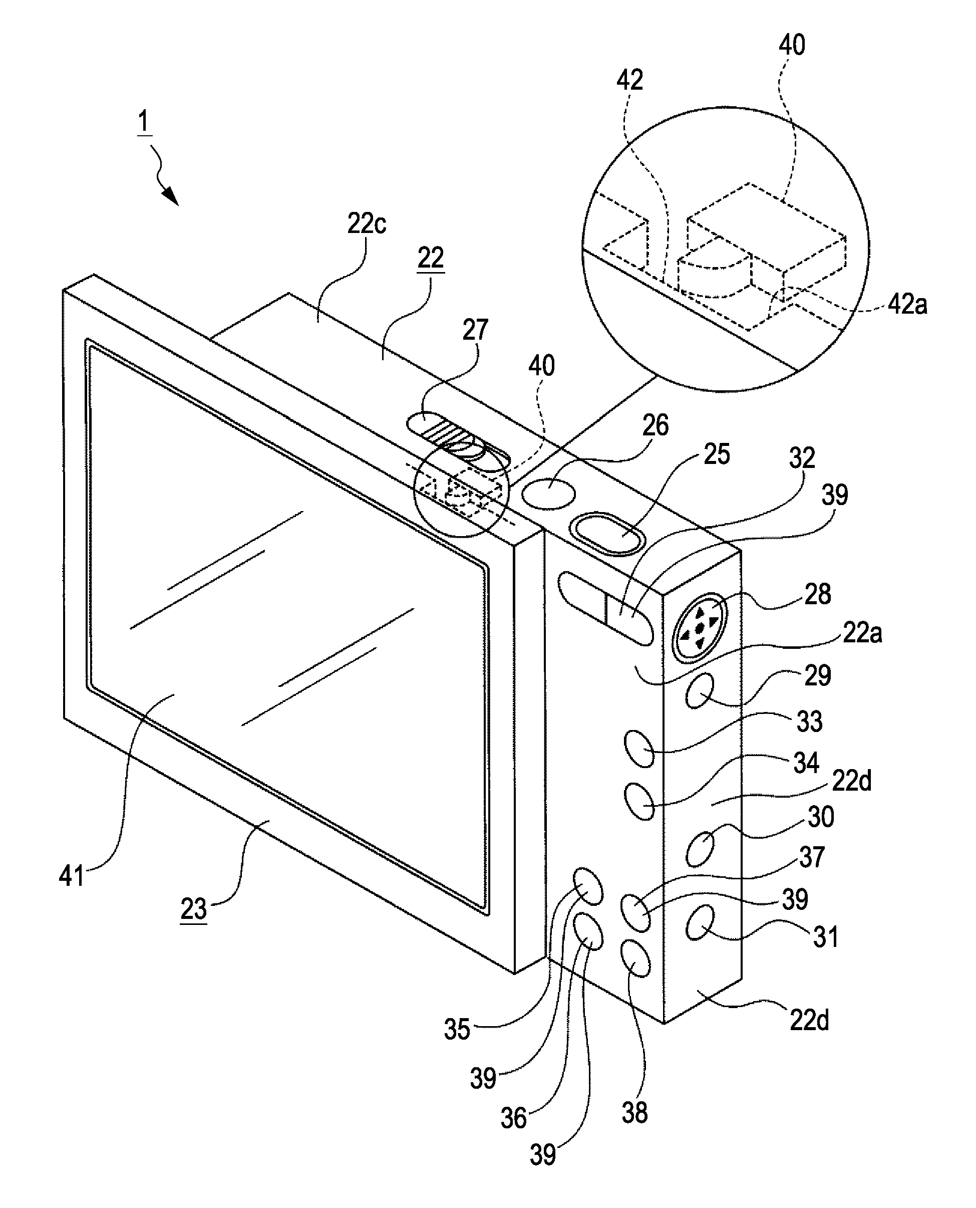
[0084]First, the architecture of an image capturing apparatus 1 (or 1A) is described with reference to FIG. 1. The image capturing apparatus 1 is an image capturing apparatus according to the first exemplary embodiment whereas the image capturing apparatus 1A is an image capturing apparatus according to a second exemplary embodiment, which will be described below.

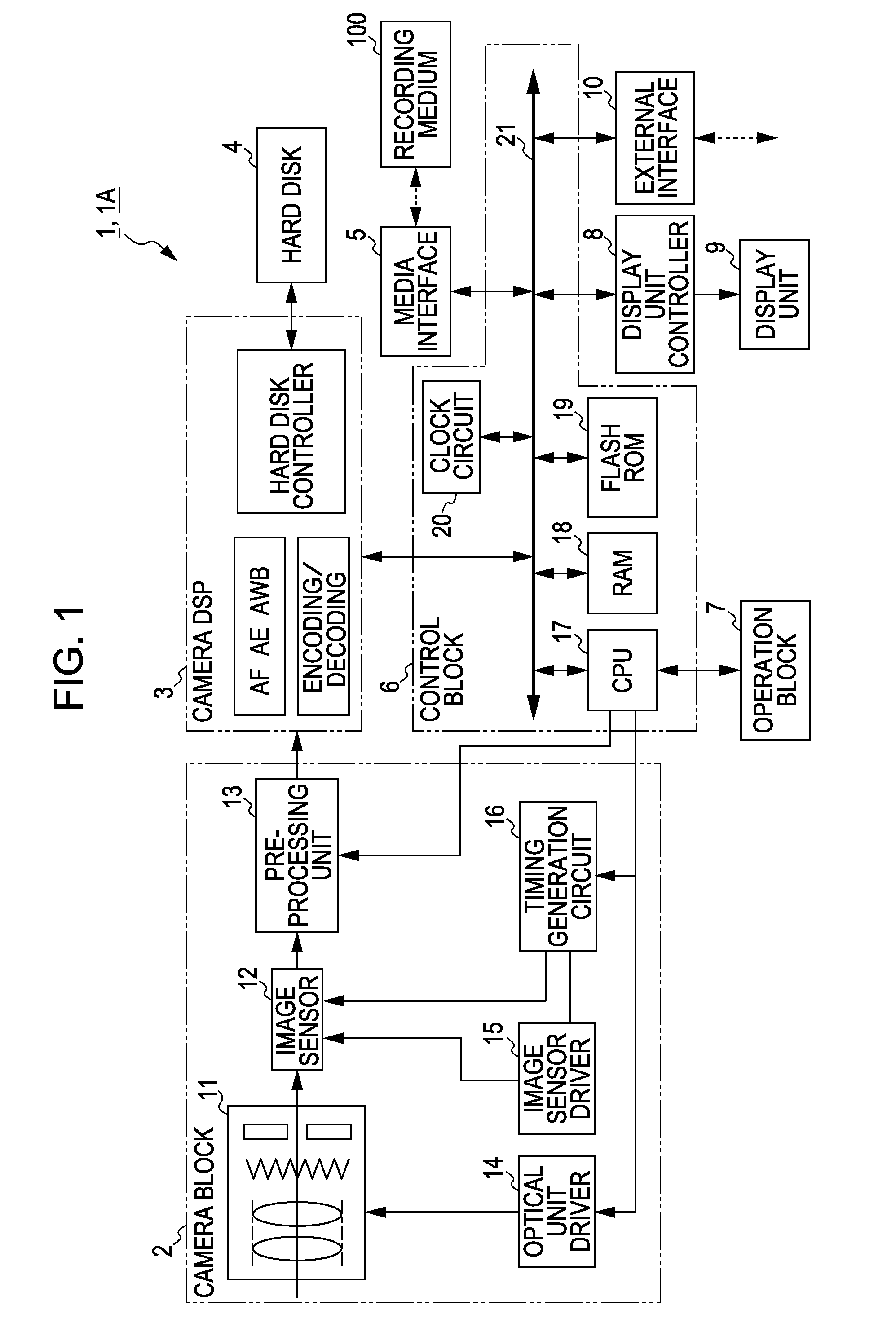
[0085]The image capturing apparatus 1 (or 1A) includes a camera block 2, a camera digital signal processor (DSP) 3, a hard disk 4, a media interface 5, a control block 6, an operation block 7, a display unit controller 8, a display unit 9, and an external interface 10. A recording medium 100 is removably mounted on the image capturing apparatus 1 (or 1A). The display unit 9 includes, for example, a liquid crystal display (LCD).

[0086]Examples of the recording medium 100 include a memory card incorporating a semiconductor memory, an opti...

second exemplary embodiment

[0166]The image capturing apparatus 1A according to a second exemplary embodiment is described next with reference to FIGS. 13 to 16.

[0167]In the following description, the components of the image capturing apparatus 1A which correspond to those of the image capturing apparatus 1 according to the first exemplary embodiment have the same reference numerals and detailed descriptions thereof are not repeated. Only the difference between the image capturing apparatus 1A and the image capturing apparatus 1 is described.

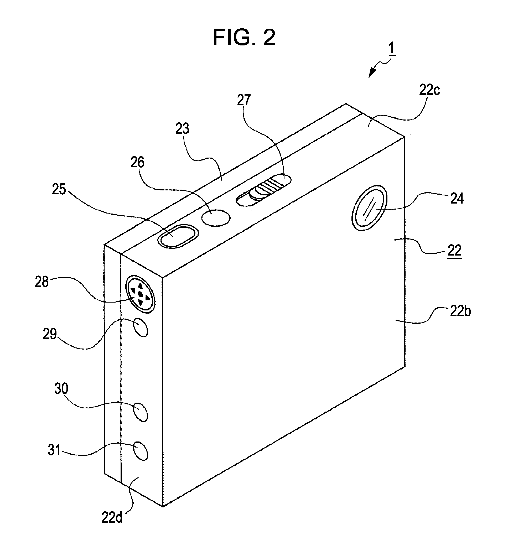
[0168]The image capturing apparatus 1A has a flat, horizontally long, substantially rectangular-parallelepiped shape. The image capturing apparatus 1A includes a camera body 57 and a slide operation unit 58 that is slidable, for example, in the right-left direction with respect to the camera body 57.

[0169]As shown in FIG. 15, an image-capturing lens 24 for capturing the image of a subject is disposed, for example, on the upper left corner of a front surface 57b of the came...

third exemplary embodiment

[0208]Image capturing apparatuses according to third to sixth embodiments of the present invention are described next with the accompanying drawings.

[0209]FIG. 17A is a front perspective view of an image capturing apparatus 1000 according to a third exemplary embodiment. FIG. 17B is a rear perspective view of the image capturing apparatus 1000 according to the third exemplary embodiment. FIG. 18A is a front perspective view of an image capturing apparatus 1000 according to a fourth exemplary embodiment. FIG. 18B is a rear perspective view of the image capturing apparatus 1000 according to the fourth exemplary embodiment. FIG. 19A is a front perspective view of an image capturing apparatus 1000 according to a fifth exemplary embodiment. FIG. 19B is a rear perspective view of the image capturing apparatus 1000 according to the fifth exemplary embodiment.

[0210]As shown in FIGS. 17A and 17B, the image capturing apparatus 1000 according to the present embodiment is a digital still camera...


PUM


Abstract

An image capturing apparatus includes a camera body having an image-capturing lens for receiving light to form an image of a subject and a display unit having a display screen for displaying the image. The display unit is slidably supported by the camera body. A surface of the display unit opposite a surface having the display screen disposed thereon faces a surface of the camera body opposite a surface having the image-capturing lens disposed thereon. An image capture button is disposed on the surface of the camera body opposite the surface having the image-capturing lens disposed thereon. The image capture button is exposed when the display unit is slid over the camera body in a first direction and the image capture button is covered by the display unit when the display unit is slid over the camera body in a second direction opposite the first direction.

Description

CROSS REFERENCES TO RELATED APPLICATIONS[0001]This application is a continuation of U.S. application Ser. No. 11 / 600,267, filed on Nov. 15, 2006, which contains subject matter related to Japanese Patent Application JP 2005-335705 filed in the Japanese Patent Office on Nov. 21, 2005, JP 2005-335706 filed in the Japanese Patent Office on Nov. 21, 2005, and JP 2005-352118 filed in the Japanese Patent Office on Dec. 6, 2005, the entire contents of which are incorporated herein by reference.BACKGROUND OF THE INVENTION[0002]1. Field of the Invention[0003]The present invention generally relates to an image capturing apparatus and, in particular, to a technology to allow a display unit having a display screen to be slidable with respect to a camera body having an image-capturing lens.[0004]2. Description of the Related Art[0005]Image capturing apparatuses (such as video cameras and still cameras) that are capable of capturing moving images or still images are in widespread use.[0006]The ima...

Claims


Application Information

Patent Timeline
Patent Type & Authority Applications(United States)
IPC IPC(8): H04N5/222
CPCH04N5/2251G03B17/04H04N23/531H04N23/00
Inventor FUKUMA, YOHEIAGATA, KENICHIYAMAMOTO, RYOKARASHIMA, TORUOTAKE, NAOHIKOOZAKI, NOZOMIMIYASHITA, HISAYAISHII, DAISUKE
Owner SONY CORP
Why Eureka
Try Eureka