
Reflecting cap for enhancing illuminance of illumination

Inactive Publication Date: 2011-05-12
KIM HENRY HYUNG KWANG +1
View PDF7 Cites 1 Cited by
  • Summary
  • Abstract
  • Description
  • Claims
  • Application Information

AI Technical Summary

Benefits of technology

[0021]The reflecting cap for enhancing an illuminance of an illumination in accordance with the present invention can enhance the illuminance and can be inserted on a lamp of various existing illuminations, thereby capable of enhancing the illuminance as well as protecting skin by UV blocking, enhancing a workability by dazzling prevention, maximizing a utilization and adjusting an irradiation angle of the light.
[0022]Also, the reflecting cap has such a structure that is used with being inserted on the lamp of the illumination and thus can functions as a lamp cover. Therefore, it can expect some buffering effect when the illumination or lamp is accidently fell, and it also can expect that an accident due to the broken pieces upon the breakage of the lamp can be prevented to some extent.
[0023]Further, it is possible to adjust an irradiation angle of the illumination light by adjusting an angle of the reflecting cap inserted on the lamp of the illumination.
[0024]Furthermore, by enhancing a diffusion effect and illuminance of the illumination, it is possible to reduce a number of the illumination used in a predetermined space and resultantly reduce power consumption, thereby capable of expecting energy saving effect. Furthermore, it is possible to reduce an amount of CO2 generated upon power generation by the reduction of power consumption, and it is thus possible to provide a reflecting cap for enhancing an illuminance of an illumination capable of reducing environmental pollution. Furthermore, since the reflecting cap is made of recyclable material, it is possible provide a reflecting cap capable of reducing the environmental pollution and being economically profitable.
[0025]In addition, by enhancing diffusion effect of illumination light through punched holes, it is possible to prevent a blur of the illumination and slim an illumination device for a billboard with expectation of reduction in a material cost according to the sliming.

Problems solved by technology

This fluorescent illumination has a predetermined illuminance to be emitted and a number of the fluorescent illumination to be quipped is determined depending on an area of the space equipped with the fluorescent illumination, and a plurality of the fluorescent illuminations is required when it is equipped in a wide space, which consumes a large amount of power.
However, this technology can increase the intensity of the light from the fluorescent illumination to some extent by reflecting the light, emitted to a direction opposite to a direction to which the fluorescent illumination lights, by a reflecting part, but has a problem that there is a limitation in an aspect of an efficiency in increasing the brightness through the reflecting panel.
However, this can expectedly increase the illuminance to some extent by reflecting the light emitted from the fluorescent illumination through the reflecting shade, but also has a problem that the increase in the illuminance through the reflecting shade cannot be largely expected.
However, this technology can expectedly enhance increase in the illuminance of the light from the fluorescent illumination, as compared to the aforementioned technologies, by forming a plurality of engraved or embossed embossing on each uneven surface of the reflecting shade, but still has a problem that there is a limitation in increasing the illuminance of the from the fluorescent illumination only through a reflecting panel.
In all of the aforementioned prior technologies for enhancing the illuminance of the light from the fluorescent illumination, there is a limitation in enhancing the illuminance of the light from the fluorescent illumination only through the reflecting shade.
Further, since the reflecting shade for enhancing the illuminance of the light from the fluorescent illumination is formed integrally with the body of the fluorescent illumination device, there is a problem that it is impossible to use it in different kinds of fluorescent illumination bodies (for example, a body of a suspended illumination, a body of a wall illumination and a body of a down illumination).

Method used


Image

  • Reflecting cap for enhancing illuminance of illumination
  • Reflecting cap for enhancing illuminance of illumination
  • Reflecting cap for enhancing illuminance of illumination

Examples


first embodiment

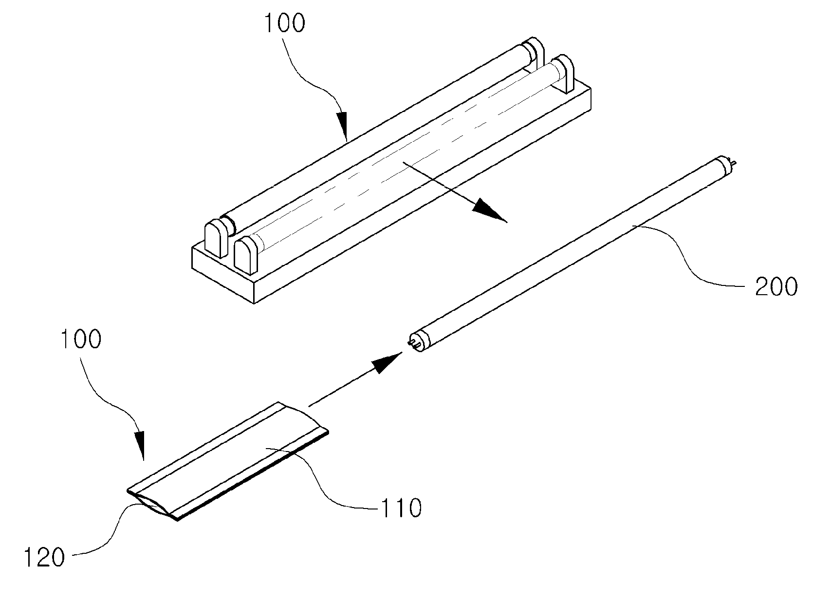
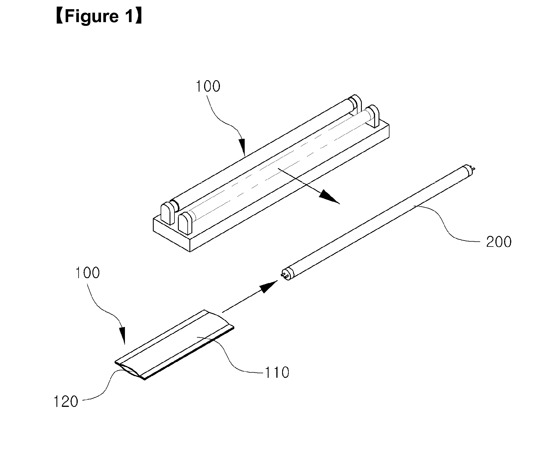
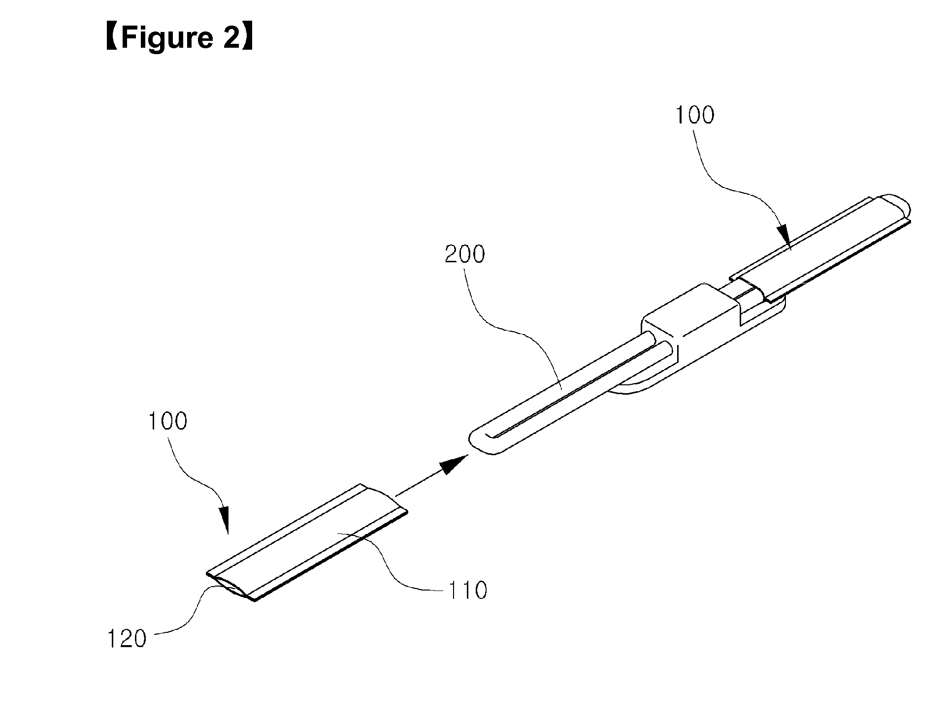
[0049]Referring to FIGS. 3 and 4, the sheet in accordance with the present invention includes the front sheet made of the diffusion film which diffuses the light emitted from the lamp of the illumination when the sheet is inserted on the lamp, and a rear sheet which is adhered with the front sheet at both ends thereof to provide the space for receiving the lamp and is made of the reflective light film for reflecting the light emitted from the lamp.

[0050]More specifically, the front sheet 110 includes a diffusion body 112 which diffuses the light emitted from the lamp of the illumination when the sheet is inserted on the lamp, and a first diffusion end 114 and a second diffusion end 116 which are formed extending from both ends of the diffusion body 112 along a length direction of the diffusion body 112 and come into contact with the rear sheet 120. Herein, the first diffusion end 114 and the second diffusion end 116, as illustrated in FIG. 4, can be formed to sizes as same as or sim...

second embodiment

[0052]FIG. 5 is a perspective view illustrating a reflecting cap for enhancing an illuminance of an illumination in accordance with the present invention, and FIG. 6 is a perspective view illustrating a reflecting cap for enhancing an illuminance of an illumination in accordance with a third embodiment of the present invention.

[0053]Referring to FIG. 5, the sheet includes the front sheet made of a punched reflective light film which diffusely transmits the light emitted from the lamp 200 when the sheet is inserted on the lamp 200 of the illumination, and the rear sheet 120 which is adhered with the front sheet at both ends thereof to provide the space for receiving the lamp and is made of the reflective light film for reflecting the light emitted from the lamp.

[0054]Referring to FIG. 6, in another embodiment, both the front sheet 110 and the rear sheet 120 can be formed of the punched reflective light film, and it is possible to give uniform illuminance in a wade area as the light i...

third embodiment

[0058]However, since a separate process of punching the reflective light film is required and the process takes cost, a separate punching is not necessary if a diffusion film with excellent diffusion performance, instead of the punched reflective light film, is used as a double sided sheet so that the light is diffused uniformly to the front side and rear side like the At this time, the diffusion film with excellent diffusion performance can employ a PET film, and specifically, CH283 (product name).

[0059]When the diffusion film with excellent diffusion performance is used as described above, since the light is diffused uniformly towards both sides and thus less number of the fluorescent illuminations can be used in the in cases of a signboard, a billboard in a bus stop and a standing board, it is possible to save energy and a blur of the fluorescent illumination is not generated due to the excellent diffusion performance even though some of the fluorescent illuminations is broken.


PUM


Abstract

The present invention relates to a reflecting cap for enhancing an illuminance of an illumination, which can enhancing the illuminance, protect skin by UV blocking, prevent dazzling, used with being inserted on lamp of various existing illuminations and adjust an irradiation angle of the light freely. To this end, the present invention provides a reflecting cap for enhancing an illuminance of an illumination, which includes a sheet having a shape that is inserted on a lamp of an illumination so as to enhance an illuminance of the illumination. In accordance with the present invention, an illuminance is increased and an economic effect can thus be expected. Further, it is possible to adjust an irradiation angle of the illumination light by adjusting an angle of the sheet inserted on the lamp of the illumination.

Description

TECHNICAL FIELD[0001]The present invention relates to a reflecting cap having a function of enhancing an illuminance of an illumination and function of blocking ultra violet light (UV), and more particularly, to an economic reflecting cap for enhancing an illuminance of an illumination, in which an illuminance of light emitted from an illumination is enhanced by the reflection cap and utilization is maximized by inserting the reflecting cap, having a function of blocking the UV from various lamps, in an existing illumination lamp.BACKGROUND ART[0002]In general, a fluorescent illumination is equipped in offices, factories and houses to function to light the space equipped with the fluorescent illumination.[0003]This fluorescent illumination has a predetermined illuminance to be emitted and a number of the fluorescent illumination to be quipped is determined depending on an area of the space equipped with the fluorescent illumination, and a plurality of the fluorescent illuminations i...

Claims


Application Information

Patent Timeline
IPC IPC(8): F21V9/16F21V7/00
CPCF21S9/022F21V3/00F21V7/005F21V9/16F21V11/14F21Y2113/00F21V14/04F21V17/04F21Y2103/00G02B5/02G02B5/208F21V13/02F21V9/06F21V13/14F21V9/30F21V9/40
Inventor KIM, HENRY HYUNG KWANGHONG, SOON HWANG
Owner KIM HENRY HYUNG KWANG
Features
  • Generate Ideas
  • Intellectual Property
  • Life Sciences
  • Materials
  • Tech Scout
  • Unparalleled Data Quality
  • Higher Quality Content
  • 60% Fewer Hallucinations
Learn More