Enhanced LED illuminator

Active Publication Date: 2011-06-23
ALCON INC
View PDF74 Cites 19 Cited by
  • Summary
  • Abstract
  • Description
  • Claims
  • Application Information

AI Technical Summary

Benefits of technology

[0015]Other embodiments of the present invention can include a method for enhanced LED ophthalmic illumination and a system for enhanced ophthalmic illumination comprising an ophthalmic illuminator as described above and one or more illuminator probes and supporting devices, such as a user interface and control devices.
[0016]Embodiments of this invention can be implemented within a surgical machine or system for use in ophthalmic or other surgery. In particular, it is contemplated that the method and system for enhanced LED illumination of this invention can

Problems solved by technology

However, surgeons also require sufficient luminous power from the endo-illuminator to properly illuminate the surgical field within the eye.
But such conventional non-solid-state light sources have many drawbacks when used in an ophthalmic illuminator.
For example, these light sources typically have a short useful lifetime.
Because the bulbs and lamps burn out every 300-400 hours, there is a good chance they may burn out during a surgical procedure.
Thus, such failures increase the risk of harm to the patient because of the immediate lack of light and the interruption of surgery.
The bulb replacement cost is also very high in current ophthalmic endo-illuminators.
Furthermore, these prior art bulbs and lamps generate substantial amounts of heat while consuming substantial amounts of power such that current ophthalmic endo-illuminators have to be made of components capable of withstanding high temperature.
Because of the heat produced by the bulbs and lamps used in current ophthalmic illuminators, a cooling fan is typically implemented within the illuminator, which adds to the cost of production/use as well as increases the bulkiness/size of the illuminator.
This fan also generates substantial levels of noise in the operating room.
Although LED light sources thus make an attractive alternative to the conventional use of HID or halogen bulbs, their luminance is typically less than a conventional bulb source.
Thus, due to the relatively high etendue of a conventional LED and its relatively low luminance, a conventional LED light source, and particul

Method used


Image

  • Enhanced LED illuminator
  • Enhanced LED illuminator
  • Enhanced LED illuminator

Examples


Example

[0025]Preferred embodiments of the present invention are illustrated in the figures, like numerals being used to refer to like and corresponding parts of the various drawings.

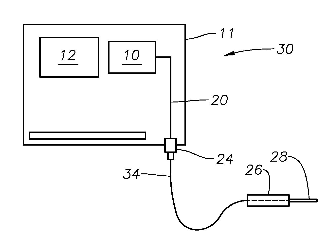
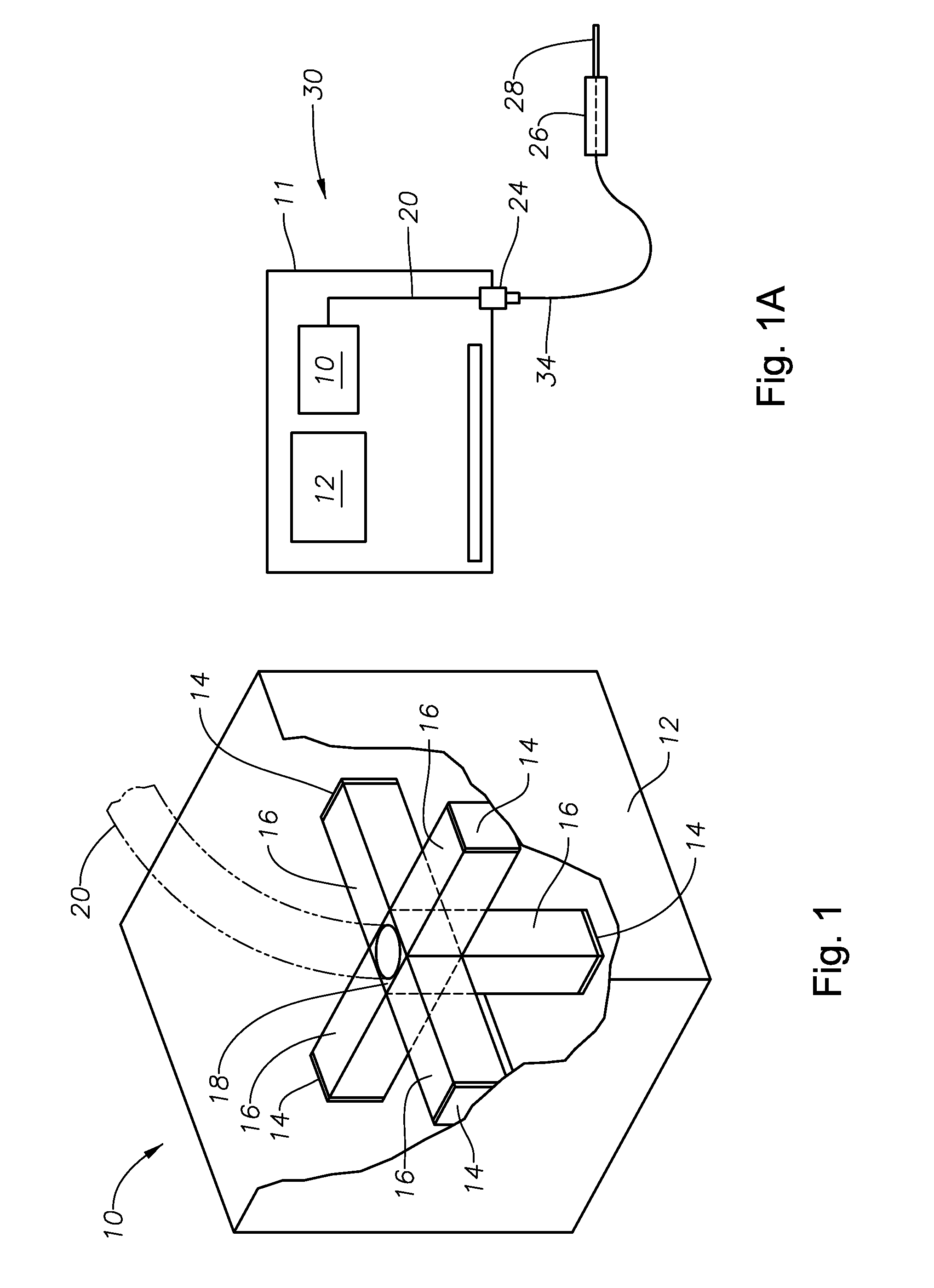
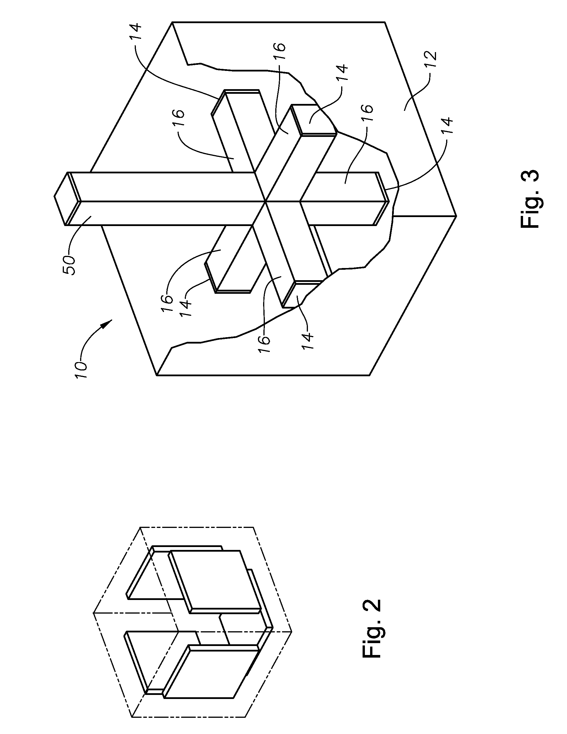
[0026]The various embodiments of the method and system for enhanced LED illumination of this invention provide an LED illumination source capable of providing light with luminance greater than the luminance of a single LED chip and efficiently coupling the light to a small diameter target, such as an optical fiber. One embodiment of the present invention is an ophthalmic illuminator comprising: an illumination source and an optical fiber for transmitting a combined light beam from the illumination source to a site, such as a surgical site within an eye, wherein the illumination source comprises a plurality of light emitting diode (LED) chips optically coupled to a corresponding plurality of light pipes, the LED chips and light pipes arranged in a configuration such that the light pipes converge together at thei...


PUM


Abstract

An ophthalmic illuminator is disclosed, one embodiment comprising: an illumination source and an optical fiber for transmitting a combined light beam from the illumination source to a site, such as a surgical site within an eye, wherein the illumination source comprises a plurality of light emitting diode (LED) chips optically coupled to a corresponding plurality of light pipes, the LED chips and light pipes arranged in a configuration such that the light pipes converge together at their distal ends to form a cubic box having five sides formed by the distal ends of the light guides and an open side from which the combined light beam, composed of light from a plurality of light beams generated by the LED chips and transmitted to the cubic box by the light guides, is emitted. The luminance of the combined light beam has a luminance greater than the luminance of any one of the plurality of LED chips.

Description

[0001]This application claims priority to U.S. Provisional Application Ser. No. 61 / 289,660 filed on Dec. 23, 2009.TECHNICAL FIELD OF THE INVENTION[0002]The present invention relates generally to the field of illumination systems. In particular, the present invention relates to ophthalmic illumination systems and, more particularly, to a system and method for enhanced LED ophthalmic illumination.BACKGROUND OF THE INVENTION[0003]Many ophthalmic surgical procedures require illuminating a portion of a patient's eye so that a surgeon can observe the surgical site. Various different types of instruments are known and available for use by an ophthalmic surgeon to illuminate the interior of the eye. Ophthalmic illuminators are commonly used for this purpose.[0004]Ophthalmic illuminators allow a surgeon to illuminate the interior structure of the eye, such as the vitreous and the retina, during surgical procedures. The handheld (probe) portion of a typical ophthalmic illuminator comprises a ...

Claims


Application Information

Patent Timeline
IPC IPC(8): F21V8/00
CPCA61B3/0008G02B23/2469G02B6/0006
Inventor SMITH, RONALD T.
Owner ALCON INC
Why Eureka
Try Eureka