This helps you quickly interpret patents by identifying the three key elements:
Problems solved by technology
Method used
Benefits of technology
Benefits of technology
The present invention allows for efficient emission and absorption of light, resulting in better use of light. This results in improved performance and efficiency of the device or system that uses the light.
Problems solved by technology
On the other hand, the liquid crystal panel, because of its nature, has a limitation in light which can be effectively used.
Method used
Image
Click on the blue label to locate the original text in one second.
Reading with bidirectional positioning of images and text.
Examples
example 1
Examination Example 1
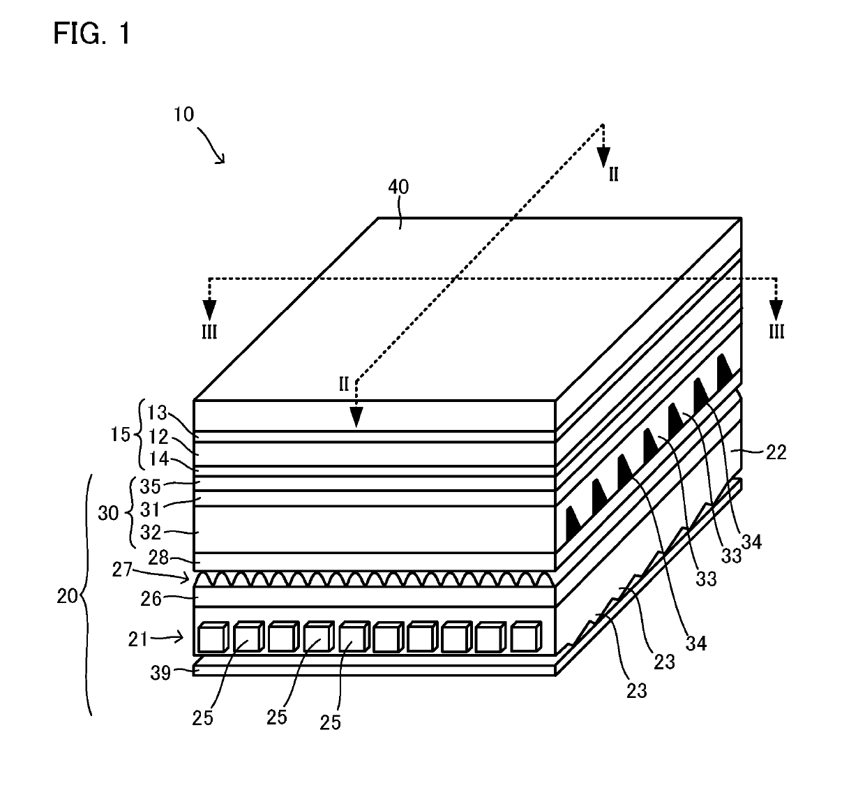
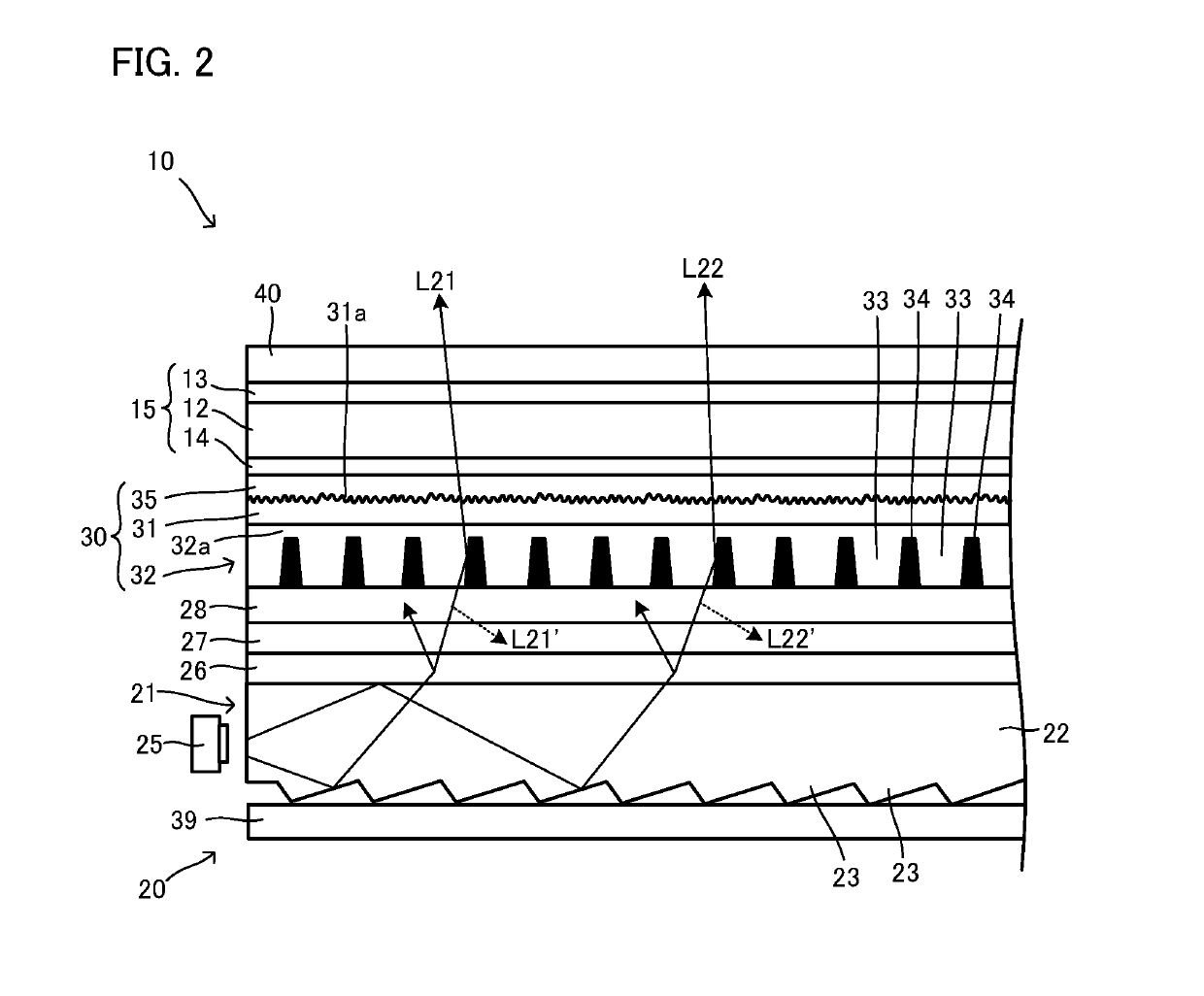
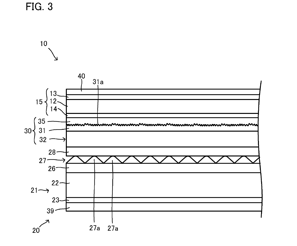
[0169]As Examination Example 1, the simulation was carried out on an image source unit corresponding to the image source unit 10 explained with reference to FIG. 1. One example of the structure of unit is as follows.
[0186]As Examination Example 2-1, an image source unit corresponding to the image source unit 10 described with reference to FIG. 1 was produced, and evaluations were carried out thereon. The specific shape was as follows.
[0187]
[0188]Material and thickness: polycarbonate, thickness 130 μm
[0191]Width of upper base of light absorbing portion: 4 μm (Wa in FIG. 7)
[0192]Width of lower base of light absorbing portion: 10 μm (Wb in FIG. 7)
[0193]Thickness of light absorbing portion: 102 μm (Dk in FIG. 7)
[0194]Thickness of optical functional layer: 127 μm
[0195]Material and refractive index of light transmissive portion: ultraviolet curable urethane acrylate of 1.56 in refractive index
[0196]Material and refractive index of light absorbing portion: carbon black-containing acrylic beads-dispersed ultraviolet curable urethane acrylate having a refractive index of 1.49, where 25 mass % of acrylic beads is dispersed in 100 mass % of the...
example 2-2
Examination Example 2-2
[0201]Examination Example 2-2 was same as Examination Example 2-1, except that θs was changed to 10°.
PUM
Abstract
A laminate including: a base material layer, an optical functional layer, and a polarizing plate; wherein the optical functional layer includes a plurality of light transmissive portions extending in one direction along a face of the base material layer, and arrayed in a direction different from an extending direction thereof, and an in-between portion(s) formed in the intervals of adjacent light transmissive portions, an angle formed by an extending direction of the transmission axis of the polarizing plate, and the extending direction of the light transmissive portions is 1° to 41.7° in a front view, the base material layer is formed of polycarbonate, and the average coefficient of linear expansion or the average linear expansion of the laminate is within a predetermined range.
Description
TECHNICAL FIELD[0001]The present disclosure relates to laminates, image source units and display devices for providing images for observers.BACKGROUND ART[0002]In a display device such as a liquid crystal television, a surface light source device illuminates a liquid crystal panel which has image information, from the back face side of the liquid crystal panel. This makes the illuminating light pass through the liquid crystal panel to obtain the image information, and is emitted to the observer side, which makes it possible for observers to see images. On the other hand, the liquid crystal panel, because of its nature, has a limitation in light which can be effectively used. Therefore improvements for efficiently using light from the light source are demanded.[0003]JP2010-217871A discloses an image source unit in which a surface light source, a prism sheet, an optical functional layer (a layer where light transmissive portions and light absorbing portions are alternately arranged), ...
Claims
Application Information
Patent Timeline
Application Date:The date an application was filed.
Publication Date:The date a patent or application was officially published.
First Publication Date:The earliest publication date of a patent with the same application number.
Issue Date:Publication date of the patent grant document.
PCT Entry Date:The Entry date of PCT National Phase.
Estimated Expiry Date:The statutory expiry date of a patent right according to the Patent Law, and it is the longest term of protection that the patent right can achieve without the termination of the patent right due to other reasons(Term extension factor has been taken into account ).
Invalid Date:Actual expiry date is based on effective date or publication date of legal transaction data of invalid patent.

