
LED light fixture

Active Publication Date: 2011-05-12
GE LIGHTING SOLUTIONS LLC
View PDF15 Cites 42 Cited by
  • Summary
  • Abstract
  • Description
  • Claims
  • Application Information

AI Technical Summary

Benefits of technology

The present disclosure provides a light emitting diode (LED) light fixture and control techniques to effectively dissipate heat generated by the LEDs and to uniformly illuminate an associated area, both horizontally and vertically, while reducing direct glare from the LED light sources.
In an exemplary embodiment, the LED light fixture includes a lens along a bottom portion of the housing. The lens may connect to the housing via a hinge which allows the lens to open and facilitate easy access to the center portion of the housing for maintenance.
The heat sink preferably includes a thermal pad which conducts heat away from the LED light source to heat dissipating fins. Because the LED strips are angled toward the center, the fins may be advantageously angularly placed on the periphery of the housing. The angled fins prevent birds from nesting on the fixture which eliminates the need for a guard or cage. Also, the angled fins allow better, vertical, airflow across the fins.
The method may further include reducing the direct glare from the LEDs by blocking direct light from a central portion of the LEDs, for example, reflecting light from a central portion of the LEDs.
Still another benefit is associated with directing light toward extremities of a light pattern where light is most needed, and the ability to precisely aim light from the small LED light sources.
Yet another benefit resides in the use of one or more of diffuse surfaces, openings or slots in the reflectors, interruptions in diffuse zone edges, and housing and reflector edge modifications that solve problems associated with linear output from LEDs that are positioned in rows or precise light placement that would otherwise cause undesirable brightness in select areas and low brightness in other areas.

Problems solved by technology

One challenge created by LED's is the dissipation of heat from the LED's.
Second, the life span of the LED is also inversely proportional to the junction temperature of an LED, so the higher the temperature, the quicker the LED degrades over time.
However, this method and arrangement may stifle airflow, which is an important factor in dissipating heat.
Also, physical obstructions, e.g., a bird nest, may be situated on a top surface created by the fins, and the nest insulates the fins which reduces the ability to dissipate the heat generated by the LEDs and drivers.
Conventional light fixtures also may adversely impact vision by producing glare.

Method used


Image

  • LED light fixture
  • LED light fixture
  • LED light fixture

Examples


Embodiment Construction

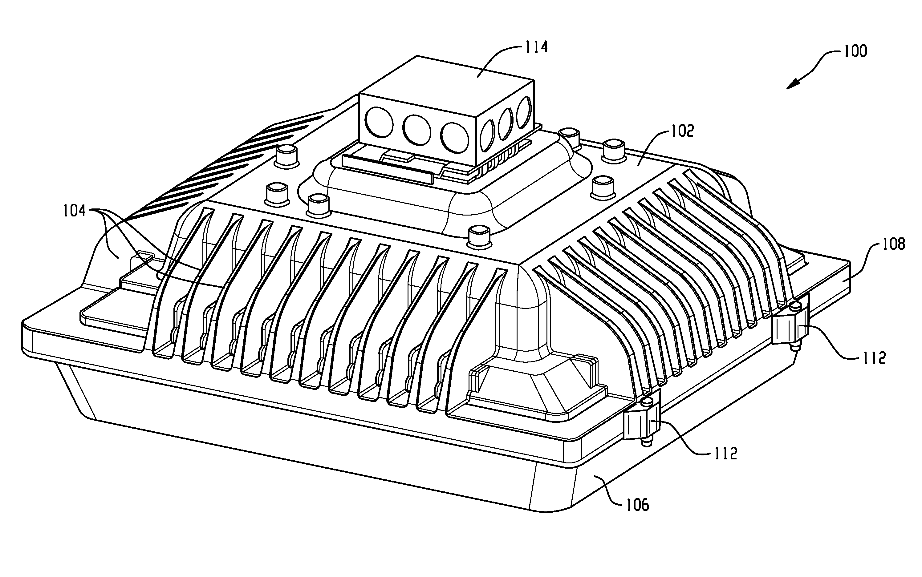
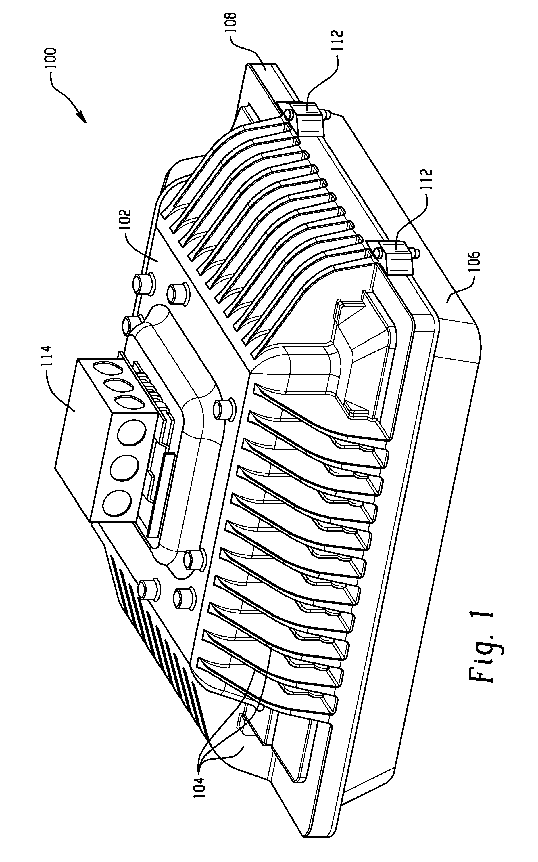
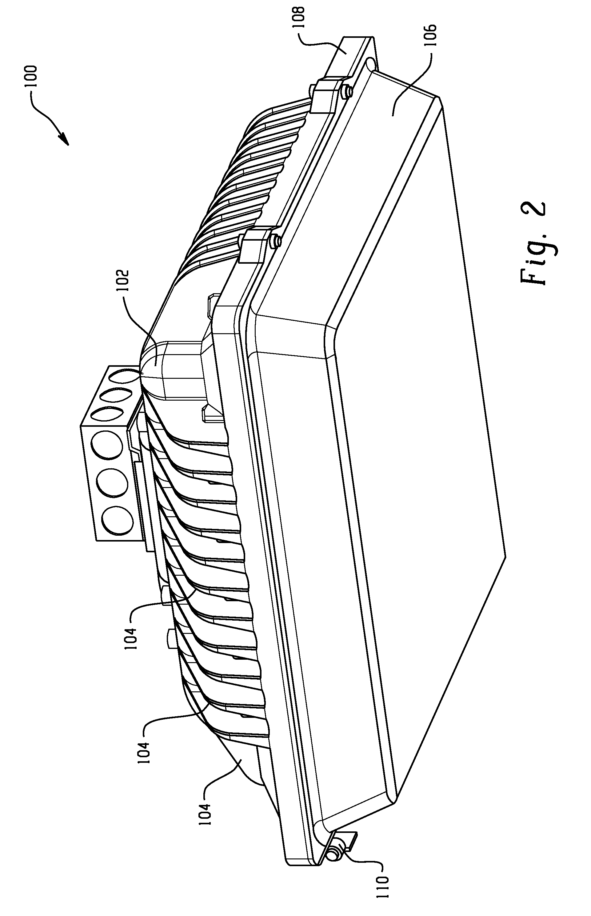
Referring now to the drawings, where like reference numerals are used to refer to like elements throughout, and wherein the various features are not necessarily drawn to scale, the present disclosure relates to light emitting diode (LED) lighting and more particularly to a light fixture that employs LEDs as a light source for illuminating a parking garage and will be described with particular reference thereto. It will be appreciated, however, that the exemplary LED light fixtures described herein can also be used in other LED lighting applications and are not limited to the aforementioned application.

Where used in the following description, it will be understood that the term “nadir” is defined as the portion of the associated area directly below the LED light fixture. Likewise, “junction temperature” is the internal temperature of the LED light source, i.e. the temperature of the P-N junction internal to the semiconductor portion of the LED.

Turning initially to FIGS. 1 and 2, an e...


PUM


Abstract

An LED light fixture and methods are provided in which the light from central portions of the LED light sources are reflected to illuminate areas on the periphery of an associated area, while less intense light from the sides of the LED light sources illuminate interior portions of the associated area to produce a uniform illumination, both horizontally and vertically, while minimizing direct glare from the light sources. The LED light fixture includes a heat sink having cooling fins on the periphery of the housing.

Description

BACKGROUND OF THE DISCLOSUREThis disclosure relates to lighting fixtures, and more particularly to lighting fixtures that employ a light source which includes distinct, multiple light sources that collectively provide a desired, adequate lumen output in a desired photometric pattern.Light fixtures have been employed to provide illumination for a wide variety of applications including, for example, parking garages to increase safety. Recently, light emitting diode (LED) technology has sufficiently advanced that LEDs may be used as the light source for these types of light fixtures. One challenge created by LED's is the dissipation of heat from the LED's. Heat has at least two detrimental effects on an LED. First, light output is inversely proportional to the junction temperature of an LED, thus the higher the temperature, the less light emitted by the LED. Second, the life span of the LED is also inversely proportional to the junction temperature of an LED, so the higher the temperat...

Claims


Application Information

Patent Timeline
IPC IPC(8): F21V1/00F21S4/00
CPCF21S2/005F21V3/00F21V5/02F21V7/0016F21V11/14F21V13/04F21V29/77F21V19/001F21V29/004F21W2131/105F21Y2101/02F21Y2103/003F21V29/763F21V17/107F21Y2103/10F21Y2115/10
Inventor BELKNAP, LEE J.TONEY, JR., JAMES H.STEINBERG, GARY ALLENWATERS, RODNEY JONATHAN
Owner GE LIGHTING SOLUTIONS LLC
Learn More