Eureka AIR delivers breakthrough ideas for toughest innovation challenges, trusted by R&D personnel around the world.

Fan and three-phase motor thereof

Active Publication Date: 2011-05-12
DELTA ELECTRONICS INC
View PDF14 Cites 4 Cited by
  • Summary
  • Abstract
  • Description
  • Claims
  • Application Information

AI Technical Summary

Benefits of technology

[0010]In view of the foregoing, the present invention is to provide a three-phase motor with a high ratio of the effective coils in the stator structure for promoting the operation efficiency, and a fan including the three-phase motor.
[0041]As mentioned above, the three-phase motor in accordance with the present invention includes the first coil assembly and the second coil assembly overlapped on the first coil assembly in the limited space of the stator structure, and one of the first coils of the first coil assembly and one of the second coils of the second coil assembly having the same phase are disposed relative to each other with an included angle. Thus, the first coil assembly and the second coil assembly can individually have the coils able to generate effective electromagnetic effects with the magnetic body of the rotor structure. In other words, the first coil assembly and the second coil assembly of the three-phase motor in accordance with the present invention have a higher ratio of the effective coils in comparison with the conventional three-phase motor. Thus, it can promote the operation efficiency of the three-phase motor, and simultaneously promote the operation efficiency of the fan including the three-phase motor in accordance with the present invention as well.

Problems solved by technology

However, the ratio of the effective coils of the three-phase coreless coil assembly 131 is frequently restricted due to the limited space of the stator structure 13 of the motor 1.
Consequentially, the operation efficiency of the motor 1 cannot be further enhanced.

Method used


Image

  • Fan and three-phase motor thereof
  • Fan and three-phase motor thereof
  • Fan and three-phase motor thereof

Examples


Embodiment Construction

[0051]The present invention will be apparent from the following detailed description, which proceeds with reference to the accompanying drawings, wherein the same references relate to the same elements.

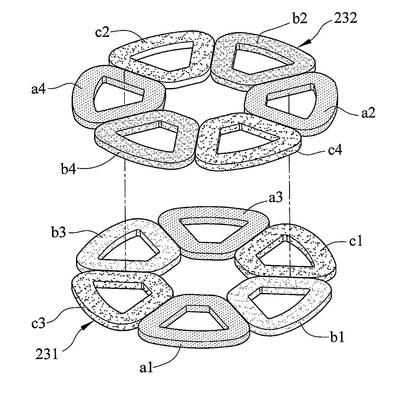
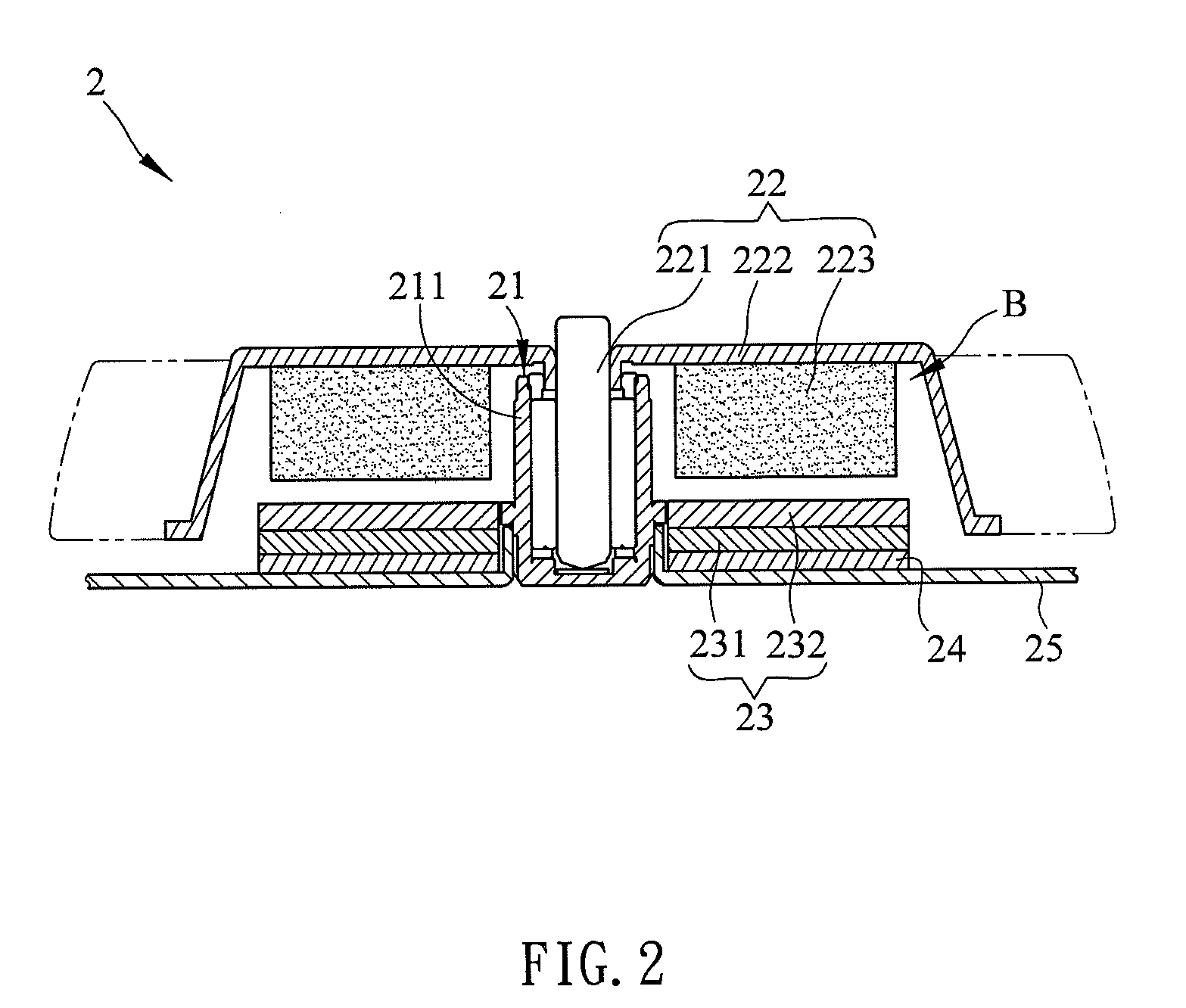
[0052]FIG. 2 is a cross-sectional figure of a three-phase motor 2 in accordance with one preferred embodiment of the present invention. As shown in FIG. 2, the motor 2 of the present invention is a three-phase coreless motor and an exterior rotor motor as well. The motor 2 of the present invention can be applied to, for example but not limited to, fans, optical disc drives, hard disk drives, optical devices, vehicle devices or other electronic devices. Moreover, the appearance and the shape of the motor 2 of the present invention are not limited, and the structure of the motor 2 can vary corresponding to applied and fields as well.

[0053]The motor 2 includes a bearing structure 21, a rotor structure 22 and a stator structure 23.

[0054]The bearing structure 21 includes a bushing 211. The...


PUM


Abstract

A three-phase motor includes a bearing structure, a rotor structure and a stator structure. The bearing structure has a bushing. The rotor structure has a shaft disposed in the bushing. The stator structure is disposed corresponding to the rotor structure and includes a first coil assembly and a second coil assembly overlapped on the first coil assembly. A fan with the motor is also disclosed. The present invention can increase the ratio of the effective coils of the stator structure, and further promote the operation efficiency of the three-phase motor and the fan with the three-phase motor.

Description

CROSS REFERENCE TO RELATED APPLICATIONS[0001]This Non-provisional application claims priority under 35 U.S.C. §119(a) on Patent Application No(s). 200910221070.9 filed in People's Republic of China on Nov. 9, 2009, the entire contents of which are hereby incorporated by reference.BACKGROUND OF THE INVENTION[0002]1. Field of Invention[0003]The present invention relates to a fan and a motor thereof and, in particular, to a fan and a three-phase coreless motor thereof.[0004]2. Related Art[0005]Motors are devices to transform electrical energy into mechanical energy, and have been applied to many products such as fans, optical disc drives, hard disk drives, optical devices or vehicle devices in daily lives. Though the motors can be classified into various types, the fundamental operation principle of the motors is electromagnetic effect.[0006]As shown in FIG. 1A, a conventional three-phase coreless motor 1 includes a bearing structure 11 and a rotor structure 12. The rotor structure 12 ...

Claims


Application Information

Patent Timeline
IPC IPC(8): F04D25/08H02K23/36H02K21/24
CPCF04D25/0606H02K21/24H02K3/47H02K3/28
Inventor LAI, CHIN-CHUNCHUANG, KUN-FUHUANG, SHIN-MING
Owner DELTA ELECTRONICS INC
Why Eureka
Eureka Blog
Learn More