
System and method for facilitating hip surgery

a hip and hip technology, applied in the field of hip surgery system and method, can solve the problems of complex hip reconstruction, exposing the patient to a risk of dislocation and revision, and reducing so as to reduce the time it takes to complete the hip surgery

Active Publication Date: 2011-05-12
MURPHY STEPHEN B
View PDF18 Cites 3 Cited by
  • Summary
  • Abstract
  • Description
  • Claims
  • Application Information

AI Technical Summary

Benefits of technology

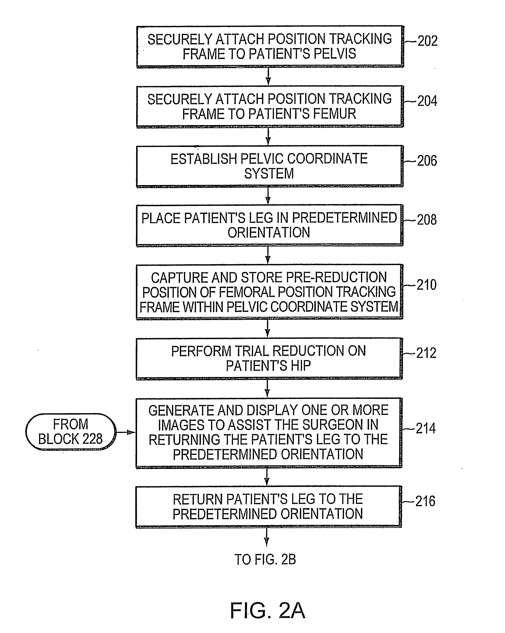
[0015]The patient's leg is then returned to the predetermined orientation. Preferably, the tracking unit, the navigation engine and the image generator all cooperate to display one or more images that guide the surgeon in returning the leg to the predetermined orientation, based upon the previously captured orientation. Once the leg is placed in the same orientation, the change in position of the reference frames compared to their original position is then purely due to linear translational changes. The leg change determination engine can therefore derive a leg length change value, an offset change value, and an AP change value. These derived values are then conveyed to the surgeon. If the derived values are not acceptable, the surgeon performs another trial reduction, e.g. by modifying the stem and head and / or the acetabular socket and directs the leg change determination engine to derive a new set of values. This process is preferably repeated until the derived change values reach acceptable levels. Significantly, the present invention does not require that a second coordinate system be established at the patient's femur, thereby substantially simplifying and reducing the time it takes to complete the hip procedure. It also avoids having to try and calculate the center of rotation of a deformed or destroyed hip joint or of the prosthetic components.

Problems solved by technology

Reconstruction of the hip, whether involving first time hip replacement or replacement of failed components, is complicated by the great mobility of is the hip joint and the uncertainty in the exact position of pelvis and femur during surgery.
Changes in leg length, offset and AP position following surgery can lead to a loose and unstable joint, exposing the patient to a risk of dislocation and revision, i.e., corrective surgery.
Unequal leg lengths can also lead to trunkal imbalance, excessively tight tissues, and discomfort.
Such physical measurements, however, are often inaccurate.
Other techniques involve the taking of images during the operation, such as X-rays, but these images are typically of unknown magnification, may not have been taken in the correct plane, and often do not show both legs on the same image, limiting the surgeon's ability to compare one side to the other.
Progression of the art has stalled though because proper establishment of a femoral coordinate system requires calculation of the center of rotation of the hip.
Unfortunately, the hip joint that is being reconstructed is often so destroyed that such a calculation is either inaccurate or impossible to determine.
It can also be time-consuming and difficult.
This method, however, is imprecise due to the difficulty in bringing the leg back into the exact same position that it was in before, thereby causing the calculation to give very inaccurate information.

Method used


Image

  • System and method for facilitating hip surgery
  • System and method for facilitating hip surgery
  • System and method for facilitating hip surgery

Examples


Embodiment Construction

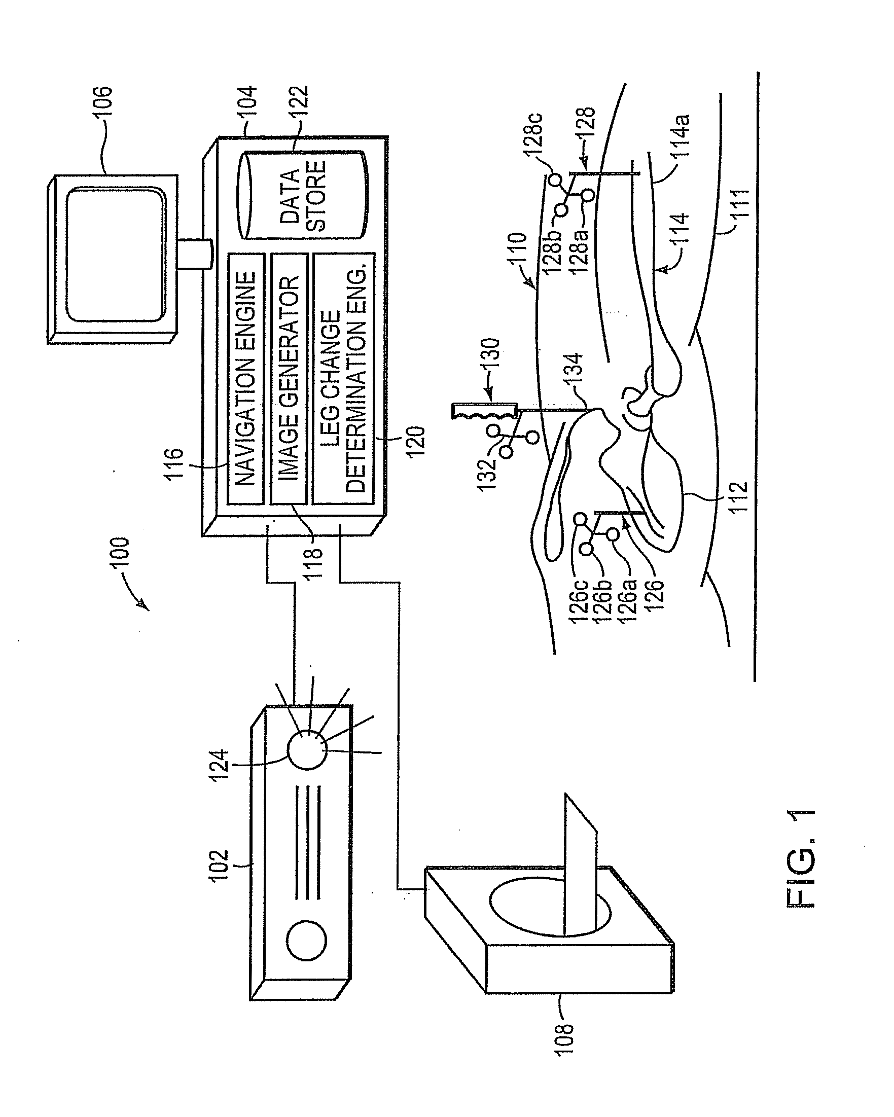
[0022]FIG. 1 is a highly schematic illustration of a system 100 for assisting in the performance of hip surgery, such as a total hip replacement, in accordance with a preferred embodiment of the invention. System 100 includes a tracking unit 102 that is coupled to a base unit 104. The base unit 104 includes a display 106. The system 100 may also include an imaging device 108 similarly coupled to the base unit 104. The imaging device 108 may be a fluoroscopic device, a magnetic resonance imaging (MRI) device, a computed tomography (CT) device, an ultrasonic device, or some other suitable imaging device. The system 100 is preferably disposed in an operating room into which a patient 110, who is to undergo hip surgery, is brought. The patient 110 has a leg 111, pelvis 112 and a femur 114, which are to be operated on.

[0023]The base unit 104 has a number of subcomponents including a navigation engine 116, an image generator 118, a leg change determination engine 120 and a data store 122....


PUM


Abstract

A system and method for use during hip surgery includes a position frame that is removably secured to the patient's femur. The system further includes a tracking unit and navigation engine that establish a pelvic coordinate system and, with the patient's leg placed in a predetermined orientation, capture the location of the femoral position frame within the pelvic coordinate system. The system further includes an image generator configured to display one or more images for directing the surgeon to return the patient's leg to the predetermined orientation following a trial reduction based upon the previously captured position. A leg change determination engine compares the current, post-reconstruction position of the femoral position tracking frame with the previously captured, pre-reconstruction position to derive leg length, offset, and anterior-posterior change values. The change values are then provided to the surgeon for evaluating the suitability of the trial reduction.

Description

CROSS-REFERENCE TO RELATED APPLICATIONS[0001]The present application is a divisional of commonly assigned copending U.S. patent application Ser. No. 11 / 351,455, which was filed on Feb. 10, 2006, by Stephen B. Murphy for a SYSTEM AND METHOD FOR FACILITATING HIP SURGERY and is hereby incorporated by reference.BACKGROUND OF THE INVENTION[0002]1. Field of the Invention[0003]The invention relates to surgical systems and methods and, more particularly, to a system and method for facilitating hip surgery.[0004]2. Background Information[0005]Hip arthritis due to malformations, fractures and diseases constitutes a major source of disability. Reconstruction of the hip, whether involving first time hip replacement or replacement of failed components, is complicated by the great mobility of is the hip joint and the uncertainty in the exact position of pelvis and femur during surgery. When a hip joint is replaced, as in total hip arthroplasty or hip resurfacing arthroplasty, critical factors to ...

Claims


Application Information

Patent Timeline
Patent Type & Authority Applications(United States)
IPC IPC(8): A61B17/56
CPCA61B5/103A61B5/6878A61B19/5244A61B2019/461A61B2019/508A61B2019/5255A61B2019/5483A61F2/36A61F2/4607A61F2/4657A61F2/4684A61F2002/4632A61F2002/4658A61F2002/4668A61B5/4528A61B34/20A61B90/06A61B90/39A61B2034/107A61B2034/108A61B2034/2055A61B2090/061A61B2090/067A61B2090/3983
Inventor MURPHY, STEPHEN B.
Owner MURPHY STEPHEN B
Learn More