System and method for secondary energy production in a compressed air energy storage system

a technology of compressed air energy storage and secondary energy, which is applied in the direction of solar thermal energy generation, steam engine plants, electrical equipment, etc., can solve the problems of not tapping other forms of energy transferred with compressed air, and the caes energy production may not be maximized

Active Publication Date: 2011-05-19
NUOVO PIGNONE TECH SRL
View PDF12 Cites 26 Cited by
  • Summary
  • Abstract
  • Description
  • Claims
  • Application Information

AI Technical Summary

Problems solved by technology

Typically, however, other forms of energy transferred with the compressed air are not tapped to produce electricity therefrom.
As such, CAES energy production may not be maximized.

Method used


Image

  • System and method for secondary energy production in a compressed air energy storage system
  • System and method for secondary energy production in a compressed air energy storage system
  • System and method for secondary energy production in a compressed air energy storage system

Examples


Embodiment Construction

[0017]Embodiments of the invention relate to adiabatic and non-adiabatic CAES systems.

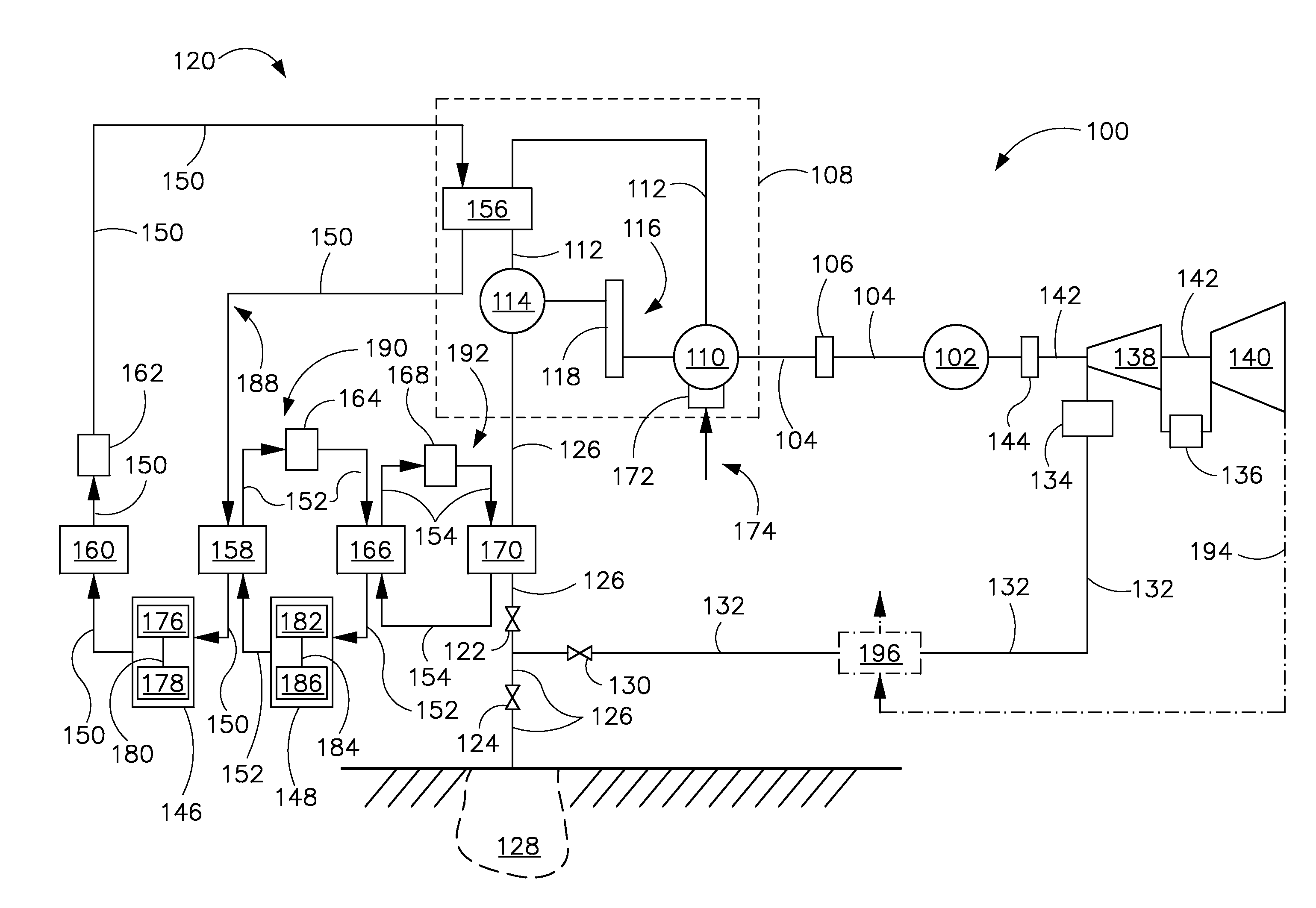
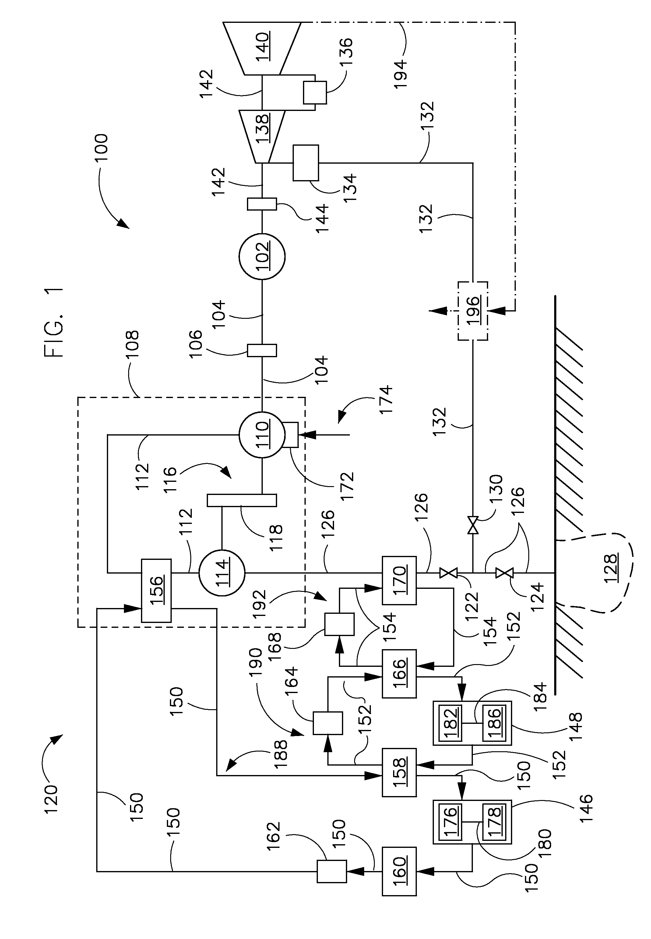
[0018]Referring to FIG. 1, a CAES system 100 is shown according to embodiments of the invention. CAES system 100 includes a motor / generator 102 and a drive shaft system 104, which has a clutch 106, and proceeds from motor / generator 102 to a compression train 108. Compression train 108 includes a first compressor 110, a compressor path 112, a second compressor 114, and a compressor drive shaft system 116 that includes a first gear box 118. CAES system 100 also includes a secondary energy or electrical production system 120, a first valve 122 and a second valve 124 along a compressed air path 126, and a storage volume 128.

[0019]Along a primary energy production stage, CAES system 100 includes a third valve 130 along a compressed air exit path 132, a first heating unit 134, and a second heating unit 136. A primary energy production system includes a first expander 138, a second expander 140, an expand...


PUM


Abstract

A method, system, and apparatus including a compressed air energy storage (CAES) system including a compression train with a compressor path, a storage volume configured to store compressed air, a compressed air path configured to provide passage of compressed air egressing from the compression train to the storage volume, and a heat recovery system coupled to at least one of the compressor path and the compressed air path and configured to draw heat from at least one of the compressor path and the compressed air path to a first liquid. The compression train is configured to provide passage of compressed air from a first compressor to a second compressor. The heat recovery system includes a first evaporator configured to evaporate the first liquid to a first gas and a first generator configured to produce electricity based on an expansion of the first gas.

Description

BACKGROUND OF THE INVENTION[0001]Embodiments of the invention relate generally to compressed air energy storage (CAES) systems and, more particularly, to secondary energy production via a CAES system.[0002]CAES systems typically include a compression train having a plurality of compressors that compress intake air and provide the compressed air to a cavern or other compressed air storage volume. The compressed air is then later used to drive turbines to produce energy such as electrical energy. Often, if utility energy is used to power the compression train, the compression train operates during off-peak hours of utility plants while the energy production or generation stage of the CAES system typically operates during high energy demand times. However, this need not be the case in every instance. For example, energy generated from wind mills may be used to power the compression train while compressed air is delivered to the energy storage cavern or the like. In any event, the econo...

Claims


Application Information

Patent Timeline
Patent Type & Authority Applications(United States)
IPC IPC(8): F02C6/16F02C1/05F02C6/02F01K11/02F01K25/08
CPCF01K3/02F01K25/00Y02E10/46H02J15/006Y02E60/15F02C6/16Y02E60/16
Inventor FREY, THOMAS JOHANNESFINKENRATH, MATTHIASAST, GABORHOFFMANN, STEPHANIE MARIE-NOELLELEHAR, MATTHEWAUMANN, RICHARD
Owner NUOVO PIGNONE TECH SRL
Why Eureka
Try Eureka