Device for cutting and removal of wires from bales

Active Publication Date: 2011-05-19
VALMET TECHNOLOGIES INC
View PDF12 Cites 9 Cited by
  • Summary
  • Abstract
  • Description
  • Claims
  • Application Information

AI Technical Summary

Benefits of technology

[0014]An additional advantage of the invention is that the driving of the different tools for winding and for cutting may be the same. The only thing that has to differ between the two devices is the head o

Problems solved by technology

It is especially important to make sure that no wire remains with the pulp since this could cause great damage to the equipment in the following process steps.
This, however, adds another step, which makes the operation sensitive to possible errors.
A problem with this device is that the arrangement does not always grip the wires correctly, or on the contrary, the wires get caught between the two parts such that the operation has to be interrupted to release the wires.
Furthermo

Method used


Image

  • Device for cutting and removal of wires from bales
  • Device for cutting and removal of wires from bales
  • Device for cutting and removal of wires from bales

Examples


Embodiment Construction

[0027]In the drawings, similar or corresponding details are indicated by the same reference signs.

[0028]In the following, the general function of the device will be described with reference to the FIGS. 1-3 and thereafter the construction and the work of the different units will be described more in detail.

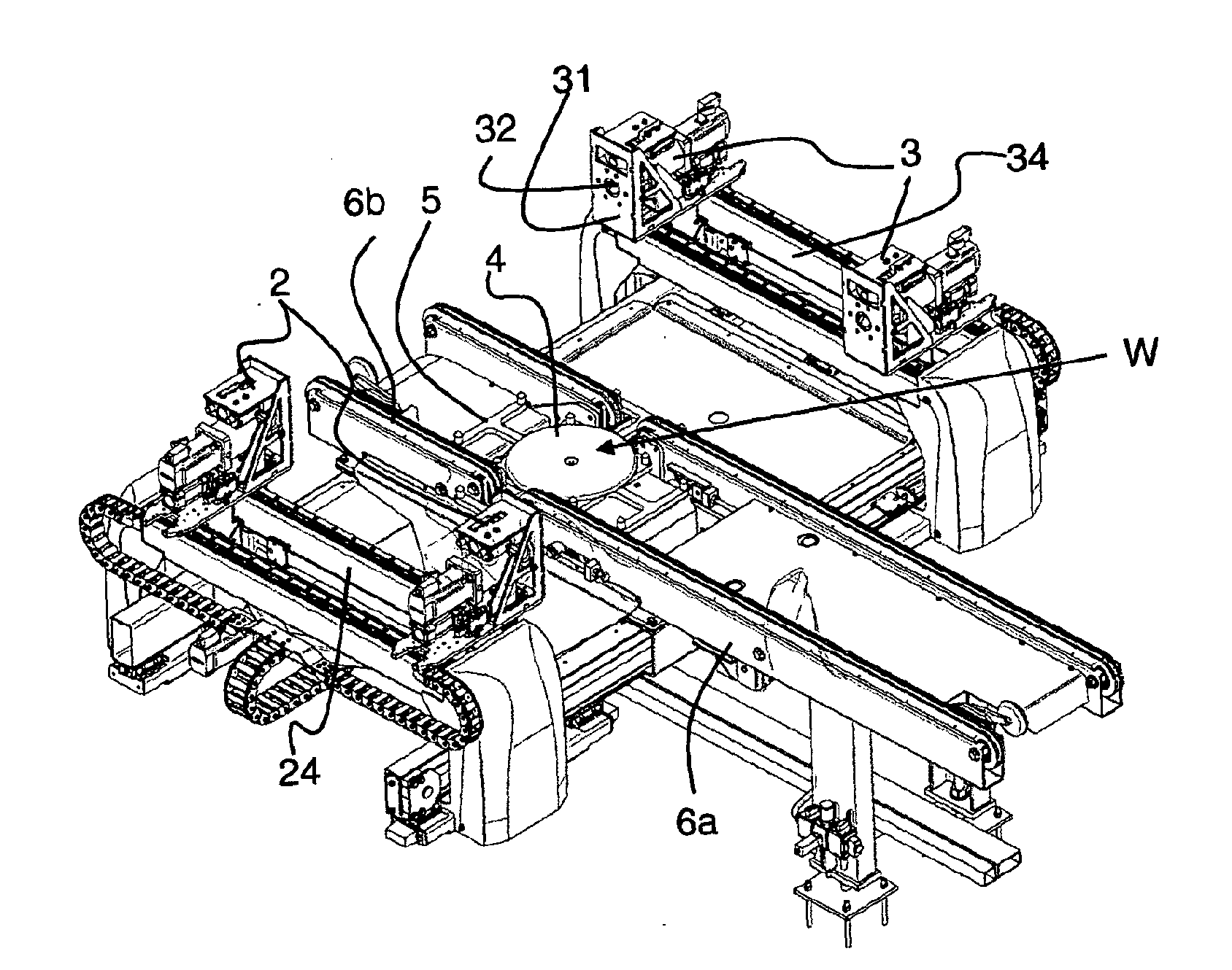
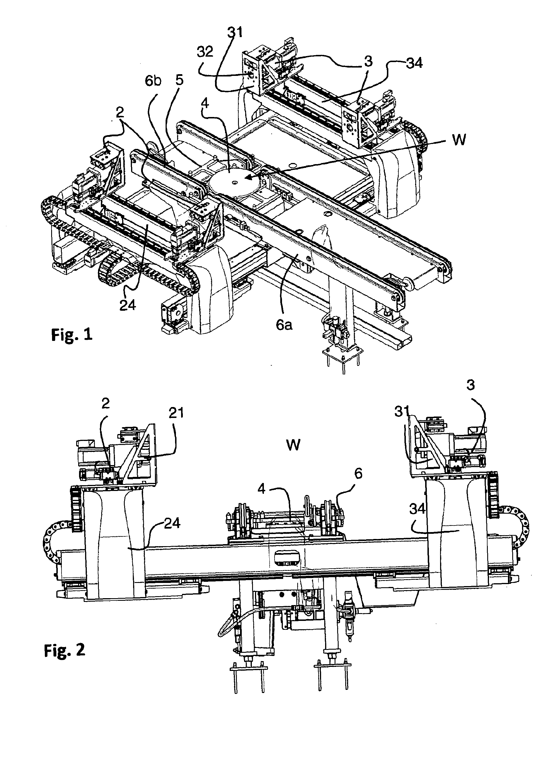
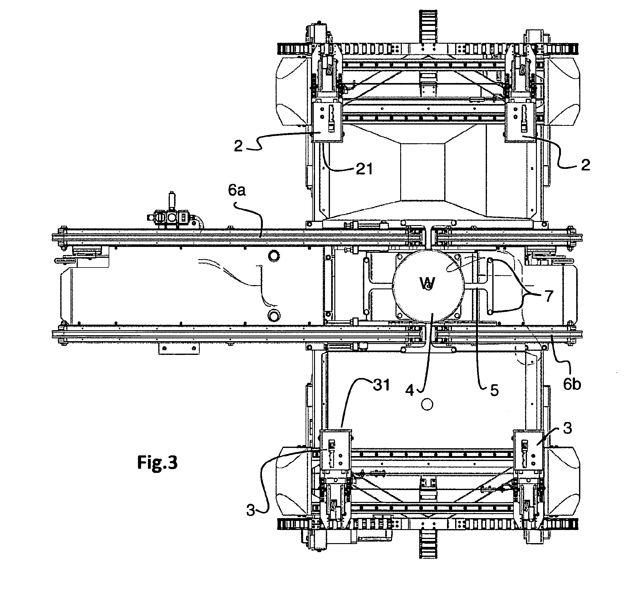
[0029]FIGS. 1-3 depict a device 1 according to the invention from different angles. The device is intended for cutting and removal of wires from bales and for this purpose, it comprises two cutting units 2 and two winding units 3. In the embodiment shown, the cutting units 2 are positioned on one side of a working location W and the winding units 3 are positioned on the other side. The working location W designates the location at which the bale is positioned when its wires are removed. The bale is transported to the working location W by means of a conveyor belt 6a. The working location comprises a sliding plate 4, and a turning tool 5, which are both vertically adjustable betwee...


PUM

PropertyMeasurementUnit
Angleaaaaaaaaaa
Timeaaaaaaaaaa
Distanceaaaaaaaaaa

Abstract

The device is for cutting and removal of wires from bales, such as pulp bales, paper bales and the like. The device is intended to remove all wires from a bale that is provided with at least two wires. The device has two cutting units and two winding units that are positioned pair-wise opposite each other, on one side each of a working location (W), for the pair-wise cutting off and removal of the two wires that are arranged in parallel.

Description

TECHNICAL FIELD[0001]The present invention relates to a device for cutting and removal of wires from bales, such as pulp bales, paper bales and the like.BACKGROUND AND PRIOR ART[0002]When pulp or paper in the form of bales is to be dissolved for the final production of paper, the wires that keep the bales together must be removed. This may be done manually or mechanically. It is especially important to make sure that no wire remains with the pulp since this could cause great damage to the equipment in the following process steps.[0003]The mechanical removal is usually carried out as a two-step operation. At first, the wires are cut off by means of one or more cutting devices and then the cut wires are removed. The removal is normally carried out by means of winding devices, which grab one end of the wire, or the centre of the wire and then rotate such that the wires are wound onto the device.[0004]One such device is known from the American patent document U.S. Pat. No. 4,850,087. Th...

Claims


Application Information

Patent Timeline
IPC IPC(8): B26D5/06B26D7/32
CPCB65B69/0025Y10T29/49821Y10T29/5139B65B57/08Y10T83/202Y10T83/538
Inventor NORBERG, MATSNORDHALLING, STEFANSTRAND, GORANJAKOBSSON, MARTIN
Owner VALMET TECHNOLOGIES INC
Why Eureka
Try Eureka