Sailing craft comprising a tilting rigid sail system

a sail system and sail technology, applied in the direction of marine propulsion, special-purpose vessels, vessel construction, etc., can solve the problems of difficult operation for a small crew or single operator, complicated cable-based rigging and stay controls

Inactive Publication Date: 2011-05-19
HANCHAR DALE WILLIAM
View PDF1 Cites 7 Cited by
  • Summary
  • Abstract
  • Description
  • Claims
  • Application Information

AI Technical Summary

Benefits of technology

[0017]12. The large surface area of the rigid sail is adaptable to coverage by flexible photo-voltaic cells permitting power generation for the electrical needs of the craft.
[0018]To overcome the deficiencies in prior art rigid sail systems and accomplish the objectives set out herein, my invention is a sail craft comprising a tilting rigid sailing system. The sailing craft has a hull having a bow and a stern, a port side and a starboard side. The tilting rigid sail system comprises a sail comprising an rigid aerofoil body capable of omni-directional attitude for wind propulsion. The rigid aerofoil body comprises a top skin and a bottom skin and a frame. The rigid aerofoil body encloses a volume of air and has a centre of gravity. The tilting rigid sail system further comprises a vertical mast for supporting the aerofoil body. The vertical mast has a top end mounting a swivel and pivot joint for connecting to the aerofoil body by way of a mounting member at a point disposed above the centre of gravity so that the aerofoil body is biased towards a horizontal position upon the loss of control line tension. The swivel and pivot joint permits and allows omni-directional attitude of the aerofoil body. The vertical mast has a bottom end fixed to the sailing craft. There is a wind force damper disposed within the top end of the vertical mast and connected to the swivel and pivot joint and hence to the aerofoil body for damping wind forces transmitted from the aerofoil body to the vertical mast. There is also aerofoil body control means for controlling the attitude of the aerofoil body for optimizing aerofoil inclination and surface area exposed to wind direction and for placing the aerofoil body in a forward propulsion attitude relative to wind direction. The aerofoil body includes floatation means disposed within the aerofoil body either as inflatable air bags or styrene panels. The aerofoil body is self weather cocking.
[0019]The aerofoil body comprises a frame, a leading edge, a trailing edge, an upper camber, an air chamber, a width, a length, a centre line, a port side, and a starboard side. The frame comprises at least four parallel ribs, including a port side rib, a starboard side rib and at least two interior ribs disposed between the port side rib and the starboard side rib. The four parallel ribs are fixed to a leading edge spar member and a spar member disposed ...

Problems solved by technology

The primary problem associated with these craft and sail systems pertains to “staying” the sails and rigging using cables and rope while allowing active portions to move freely in ord...

Method used


Image

  • Sailing craft comprising a tilting rigid sail system
  • Sailing craft comprising a tilting rigid sail system
  • Sailing craft comprising a tilting rigid sail system

Examples


Embodiment Construction

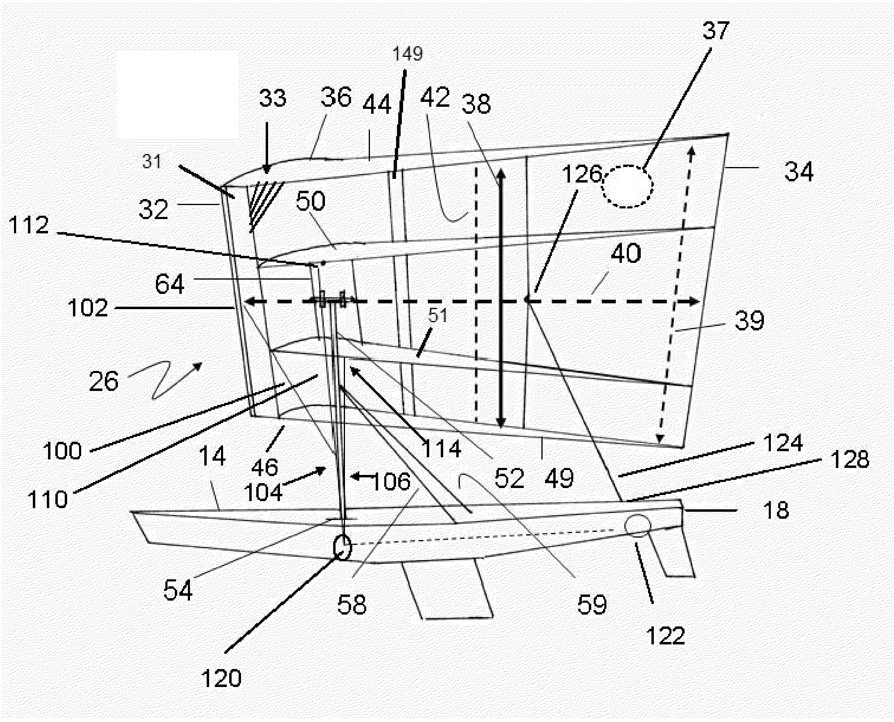
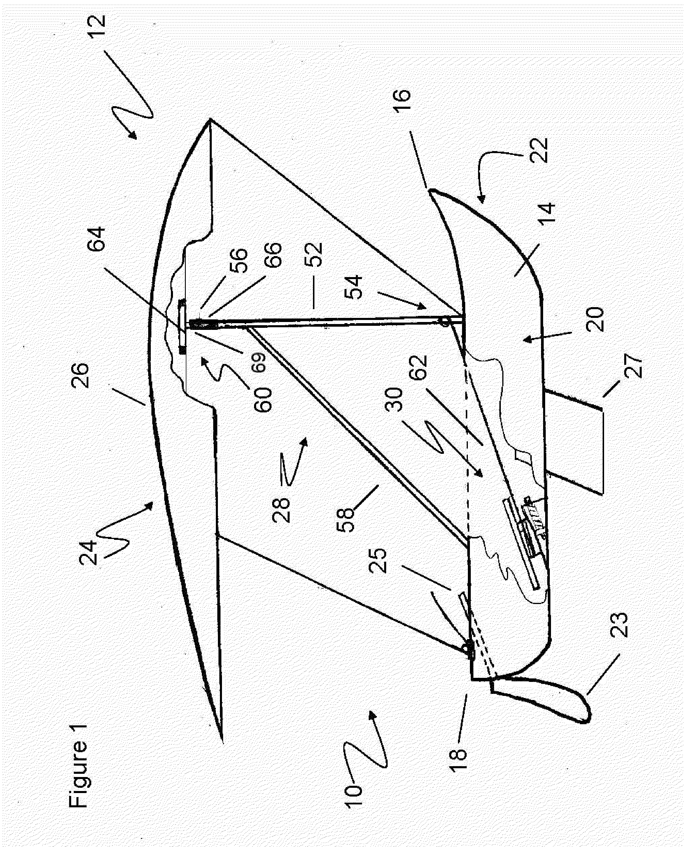
[0038]Referring to FIG. 1 there is shown in side view my invention, a sailing craft 10 comprising a tilting rigid sail system 12. The sailing craft 10 has a hull 14 having a bow 16 and a stern 18, a starboard side 20 and a port side 22. Also illustrated are rudder 23, tiller arm 25 and keel 27. The tilting sail system 12 comprises a sail 24 comprising an aerofoil body 26 capable of an omni-directional attitude for wind propulsion. The aerofoil body 26 is supported by support means 28 for fixing the aerofoil body 26 to the sailing craft 10 and permitting an omni-directional attitude of the aerofoil body. The tilting sail system further comprises aerofoil body control means 30 for placing the aerofoil body 26 in a forward propulsion attitude relative to wind direction. The aerofoil body is rigid and has an asymmetric shape. The aerofoil body is self weather cocking, that is, it will always turn itself into the wind.

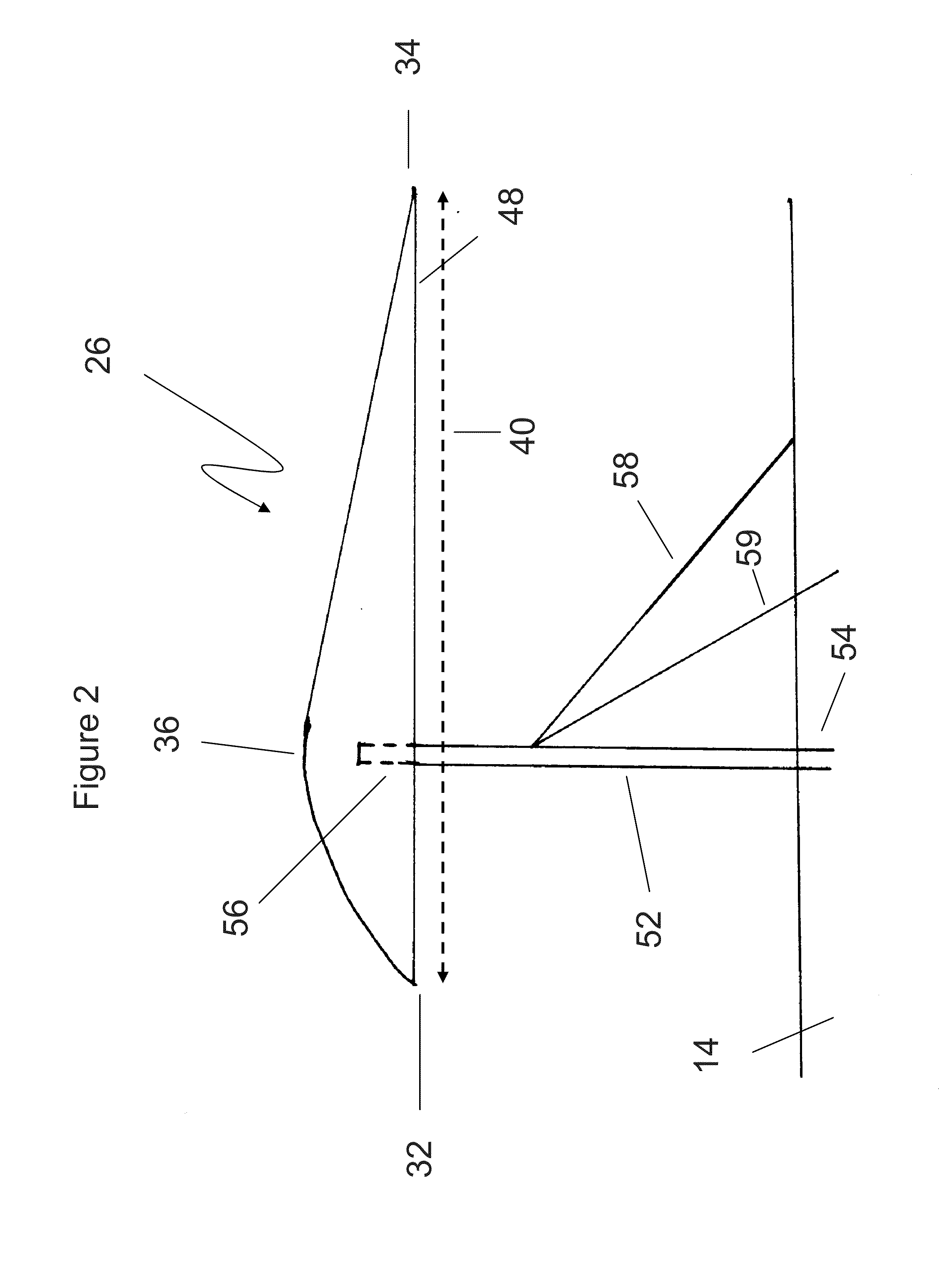
[0039]Referring to FIGS. 2 and 3, the aerofoil body 26 comprises a lea...


PUM


Abstract

A sailing craft propelled by a tilting sail system comprising an aerofoil sail capable of omni-directional attitude for wind propulsion. The sail is fixed to the craft in such a manner as to permit omni-directional attitude. Sail control means allows the sail placement in a forward propulsion attitude relative to wind direction. The sail is rigid and has an asymmetric shape.

Description

CROSS-REFERENCES TO OTHER APPLICATIONS[0001]This application is a continuation-in-part of U.S. patent application Ser. No. 11 / 955,357 filed on Dec. 12, 2007.FIELD OF THE INVENTION[0002]This invention pertains to sailing craft and tilting sail systems and more particularly to a sailing craft comprising a tilting rigid sail system.BACKGROUND OF THE INVENTION[0003]Sailing craft and sail systems are well known. The idea of putting a rigid aerofoil-type sail on a sailing craft is discussed in U.S. Pat. No. 2,170,914 issued to Rummler and U.S. Pat. No. 1,670,936 issued to M. McIntyre et al. The primary problem associated with these craft and sail systems pertains to “staying” the sails and rigging using cables and rope while allowing active portions to move freely in order to operate properly. As illustrated by U.S. Pat. No. 4,068,607 the cable-based rigging and stay controls are very complicated and difficult for a small crew or single operator to operate.[0004]What is therefore required...

Claims


Application Information

Patent Timeline
IPC IPC(8): B63H9/04B63H9/06
CPCB63H2009/0621B63H9/0685B63H9/0621B63H9/068
Inventor HANCHAR, DALE WILLIAM
Owner HANCHAR DALE WILLIAM
Why Eureka
Try Eureka