Vibratory separator motion

a vibrating separator and motion technology, applied in the direction of solid separation, chemistry apparatus and processes, borehole/well accessories, etc., can solve the problems of time-consuming and expensive mud evaluation and mixture process, too light may not protect, and too heavy may over-invade the formation

Inactive Publication Date: 2011-05-19
MI
View PDF7 Cites 23 Cited by
  • Summary
  • Abstract
  • Description
  • Claims
  • Application Information

AI Technical Summary

Benefits of technology

In one aspect, embodiments disclosed herein relate to a vibratory separator including a first actuator coupled to a basket and a second actuator coupled to the basket. Additionally, the vibratory separator includes a motion control switch operatively connected to at least one of the first and second actuators and configured to modulate motion generated by the first and second actuators between a first elliptical motion and a second elliptical motion.

Problems solved by technology

Drilling mud that is too light may not protect the formation from blow outs, and drilling mud that is too heavy may over invade the formation.
Because the mud evaluation and mixture process is time consuming and expensive, drillers and service companies prefer to reclaim the returned drilling mud and recycle it for continued use.
However, in certain separatory operations, the weight of solids may still restrict the speed that linear motion separation provides.
Additionally, while increased G-forces enable faster conveyance, as the speed of conveyance increases, there is a potential that the produced drilled solids may still be saturated in drilling fluid.
However, such lower force vibrations generally slow drilling material processing, thereby increasing the time and cost associated with processing drilling material.

Method used


Image

  • Vibratory separator motion
  • Vibratory separator motion
  • Vibratory separator motion

Examples


Embodiment Construction

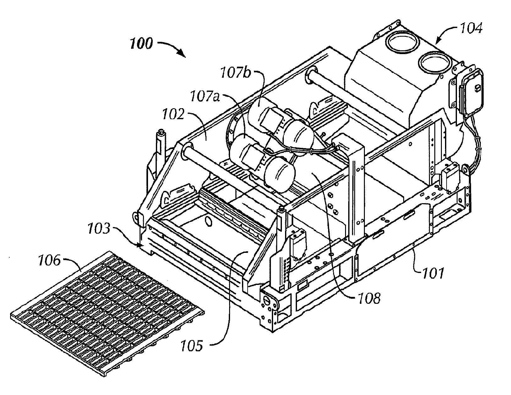
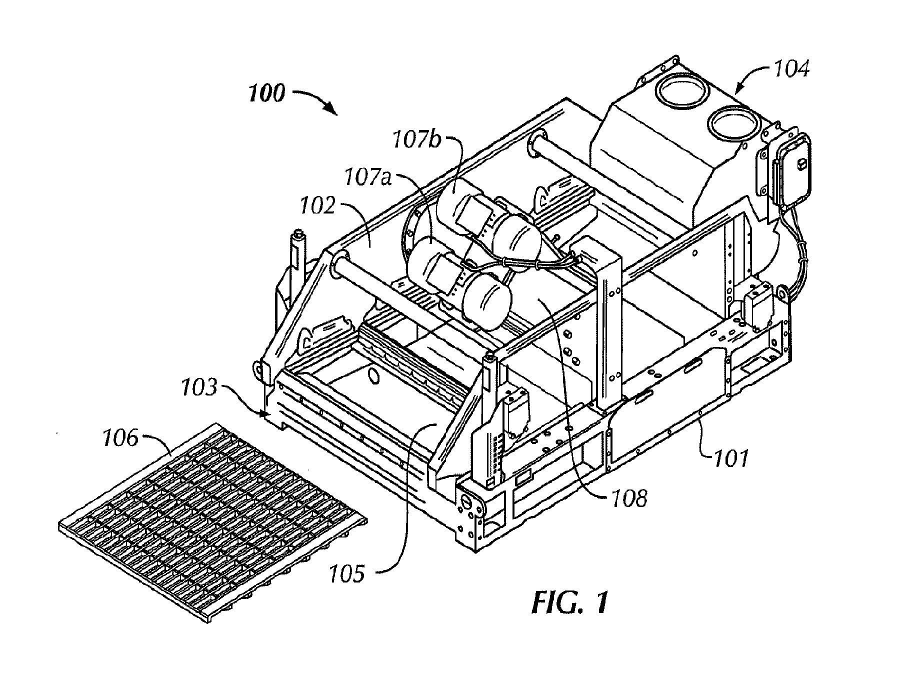
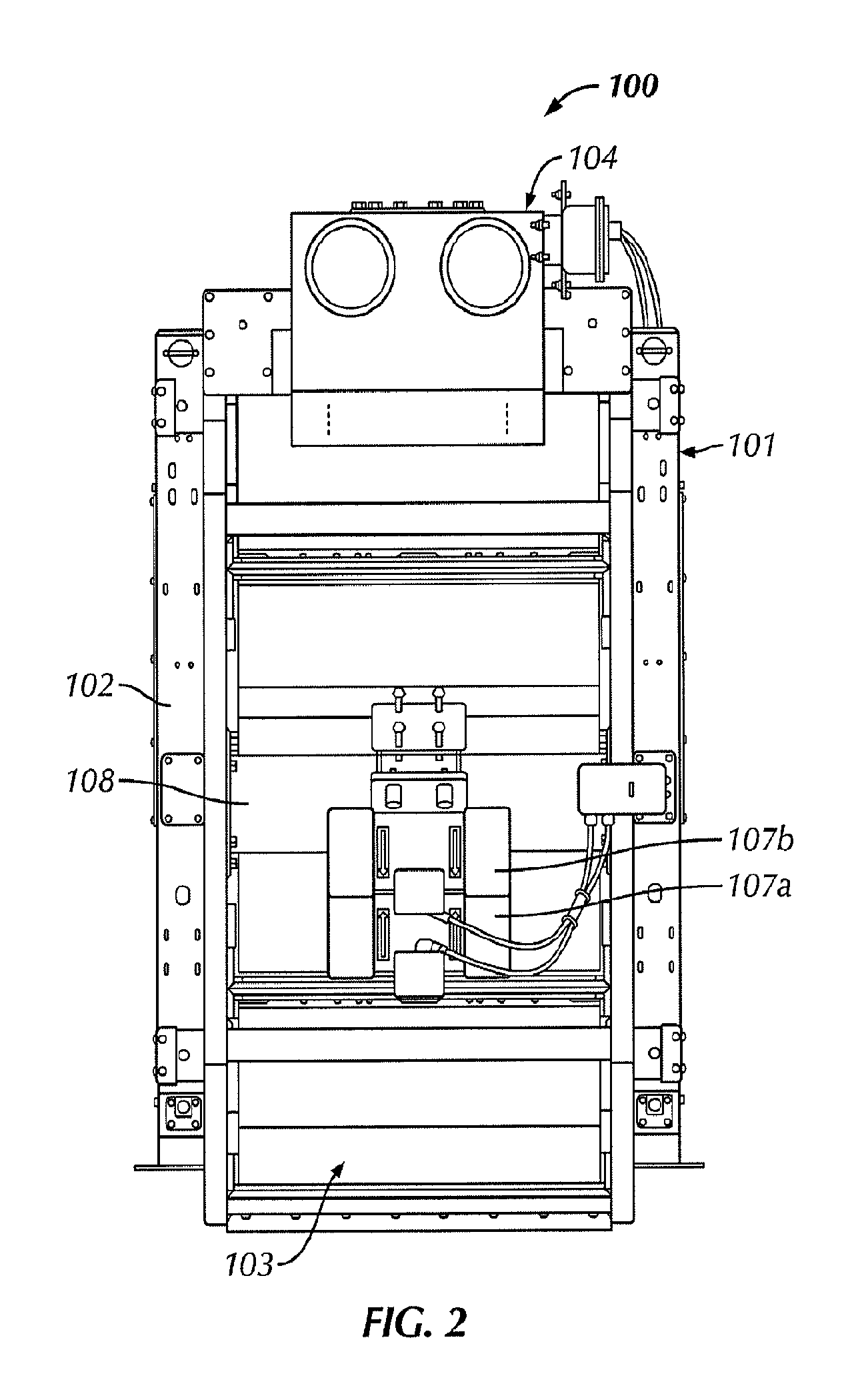
Generally, embodiments disclosed herein relate to apparatuses and methods for separating solids from liquids. Specifically, embodiments disclosed herein relate to apparatuses and methods for separating solids from liquids using dual motion profiles on vibratory separators. More specifically still, embodiments disclosed herein relate to apparatuses and methods for producing a first elliptical motion and a second elliptical motion on vibratory separators.

Traditionally, vibratory separators have been designed to produce a specific type of motion, for example, linear, circular, unbalanced elliptical, or balanced elliptical. The type of motion was dictated by the placement of actuators relative to the vibratory separator body, and as such, the shape of the motion could only be changed by physically altering the configuration / placement of the actuators. Typically, vibratory separators capable of generating a single type of motion use one or two motors positioned at a specific location on ...


PUM


Abstract

A vibratory separator (100) including a first actuator (107A) coupled to a basket (105) and a second actuator (107B) coupled to the basket. Additionally, the vibratory separator (100) includes a motion control switch operatively connected to at least one of the first and second actuators (107A, 107B) and configured to modulate motion generated by the first and second actuators between a first elliptical motion and a second elliptical motion. Also, a method of processing drilling waste, the method including flowing drilling waste over a screen of a vibratory separator and imparting a first elliptical motion to the screen. The method further includes monitoring the flow of drilling waste over the screen, determining an overload condition exists, and adjusting the motion to a second elliptical motion based on the determined load condition.

Description

BACKGROUND1. Field of the DisclosureEmbodiments disclosed herein relate generally to apparatuses and methods for separating solids from liquids. Specifically, embodiments disclosed herein relate to apparatuses and methods for separating solids from liquids using dual motion profiles on vibratory separators. More specifically still, embodiments disclosed herein relate to apparatuses and methods for producing a first elliptical motion and a second elliptical motion on vibratory separators.Background ArtOilfield drilling fluid, often called “mud,” serves multiple purposes in the industry. Among its many functions, the drilling mud acts as a lubricant to cool rotary drill bits and facilitate faster cutting rates. Typically, the mud is mixed at the surface and pumped downhole at high pressure to the drill bit through a bore of the drillstring. Once the mud reaches the drill bit, it exits through various nozzles and ports where it lubricates and cools the drill bit. After exiting through ...

Claims


Application Information

Patent Timeline
Patent Type & Authority Applications(United States)
IPC IPC(8): B07B1/42E21B21/06
CPCE21B21/065B07B1/42
Inventor CARR, BRIAN S.TIMMERMAN, MICHAEL A.HOLTON, BENJAMIN L.
Owner MI
Why Eureka
Try Eureka