Vehicular power supply circuit

a power supply circuit and power supply circuit technology, applied in the direction of engine-driven generators, electric devices, transportation and packaging, etc., can solve the problems of increasing the cost of the the difficulty of integrating the noise protection circuit for the load into a common noise protection circuit, and the cost of the conventional power supply circuit as a whol

Inactive Publication Date: 2011-05-19
ANDEN CORP +1
View PDF4 Cites 12 Cited by
  • Summary
  • Abstract
  • Description
  • Claims
  • Application Information

AI Technical Summary

Problems solved by technology

Therefore, it is difficult to integrate noise protection circuits for the loads into a common noise protection circuit on the upstream side of the power supply circuit.
As a result, each load needs to have an individual noise protection circuit, and the power supply circuit as a whole is increased in cost.
As a result, the conventional power supply circuit as a whole is increased in cost.
Addition of such a large diode to each of the power loads 110-112 can result in a large increase in cost.

Method used


Image

  • Vehicular power supply circuit
  • Vehicular power supply circuit
  • Vehicular power supply circuit

Examples


embodiment

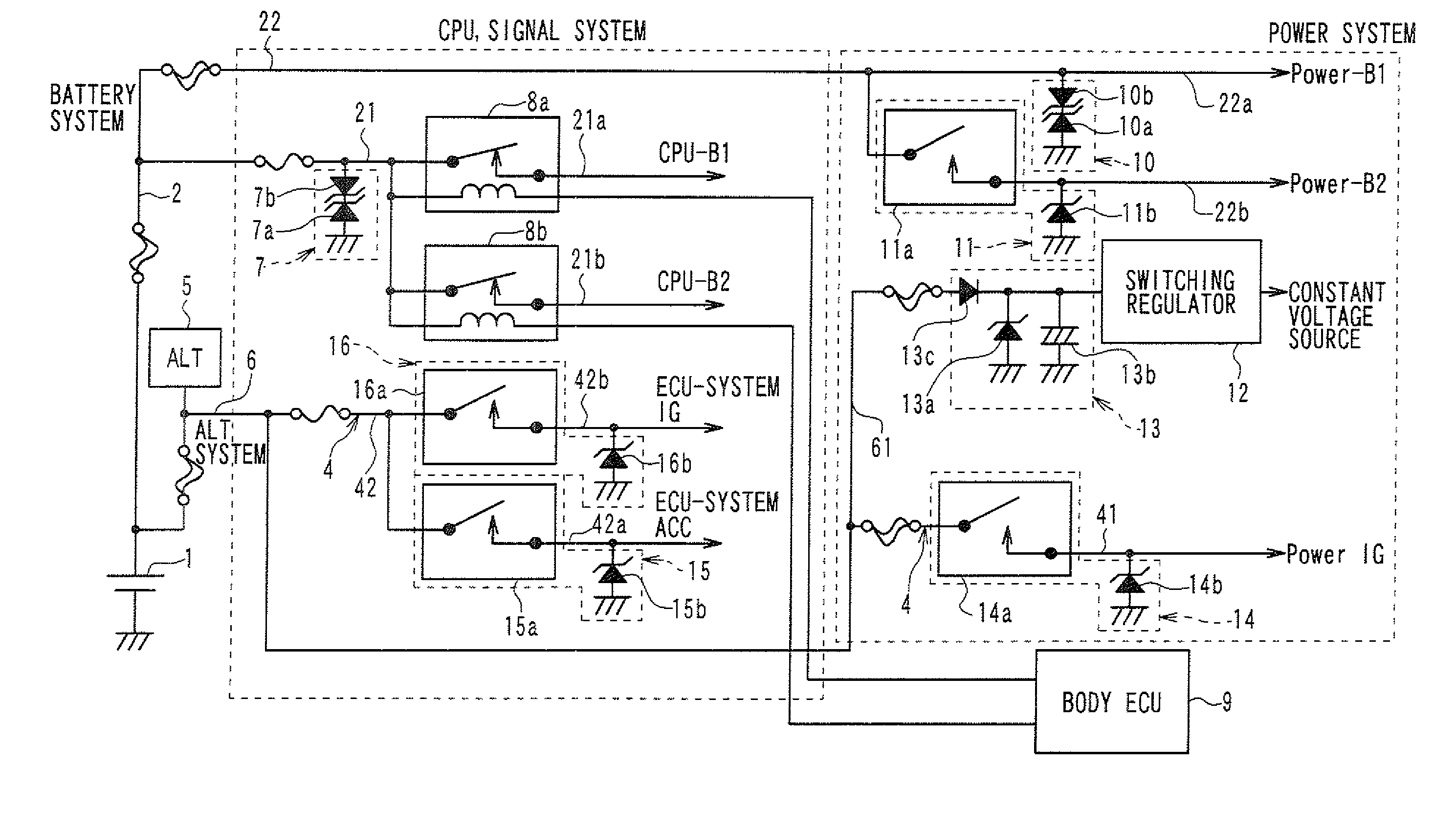
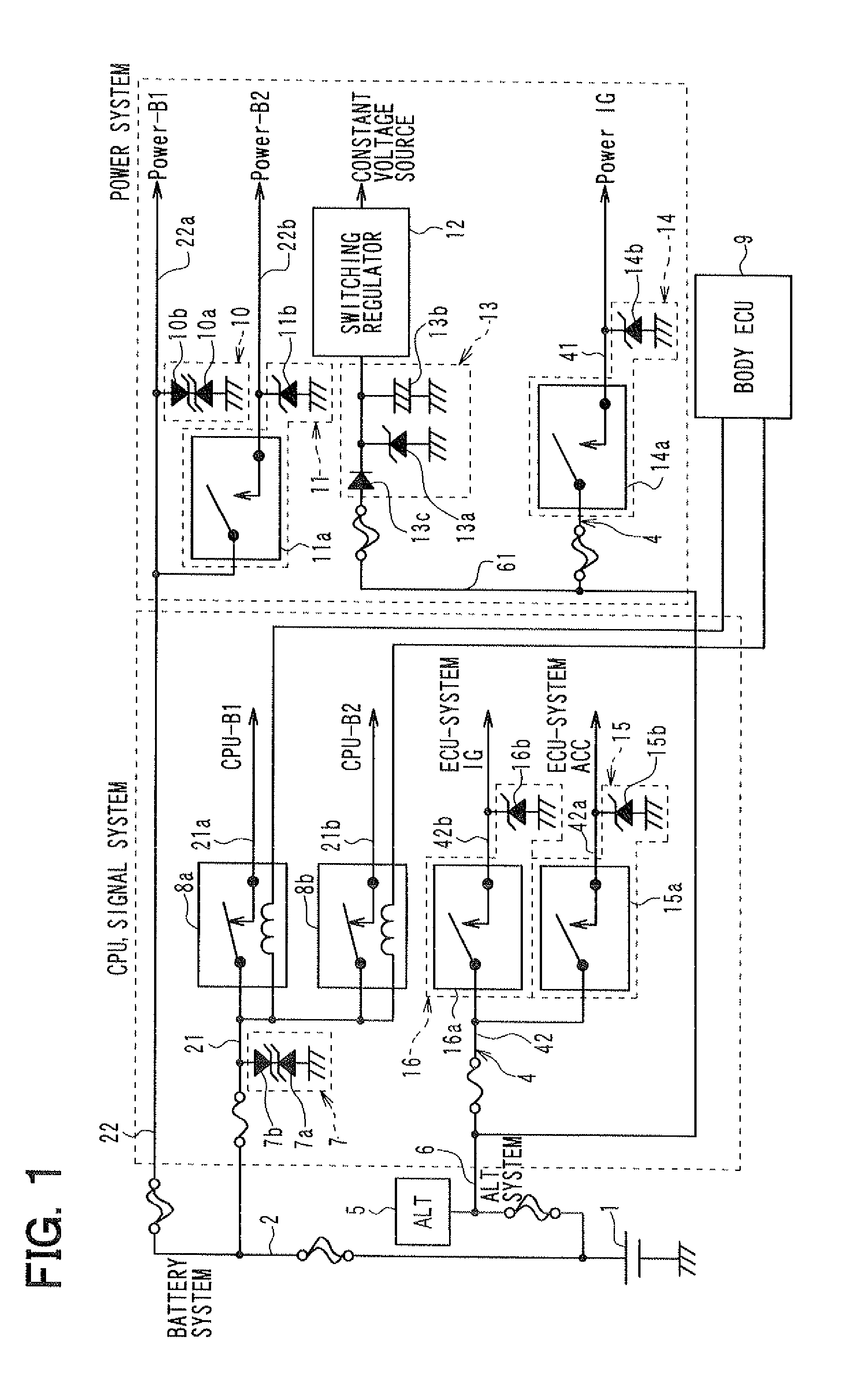
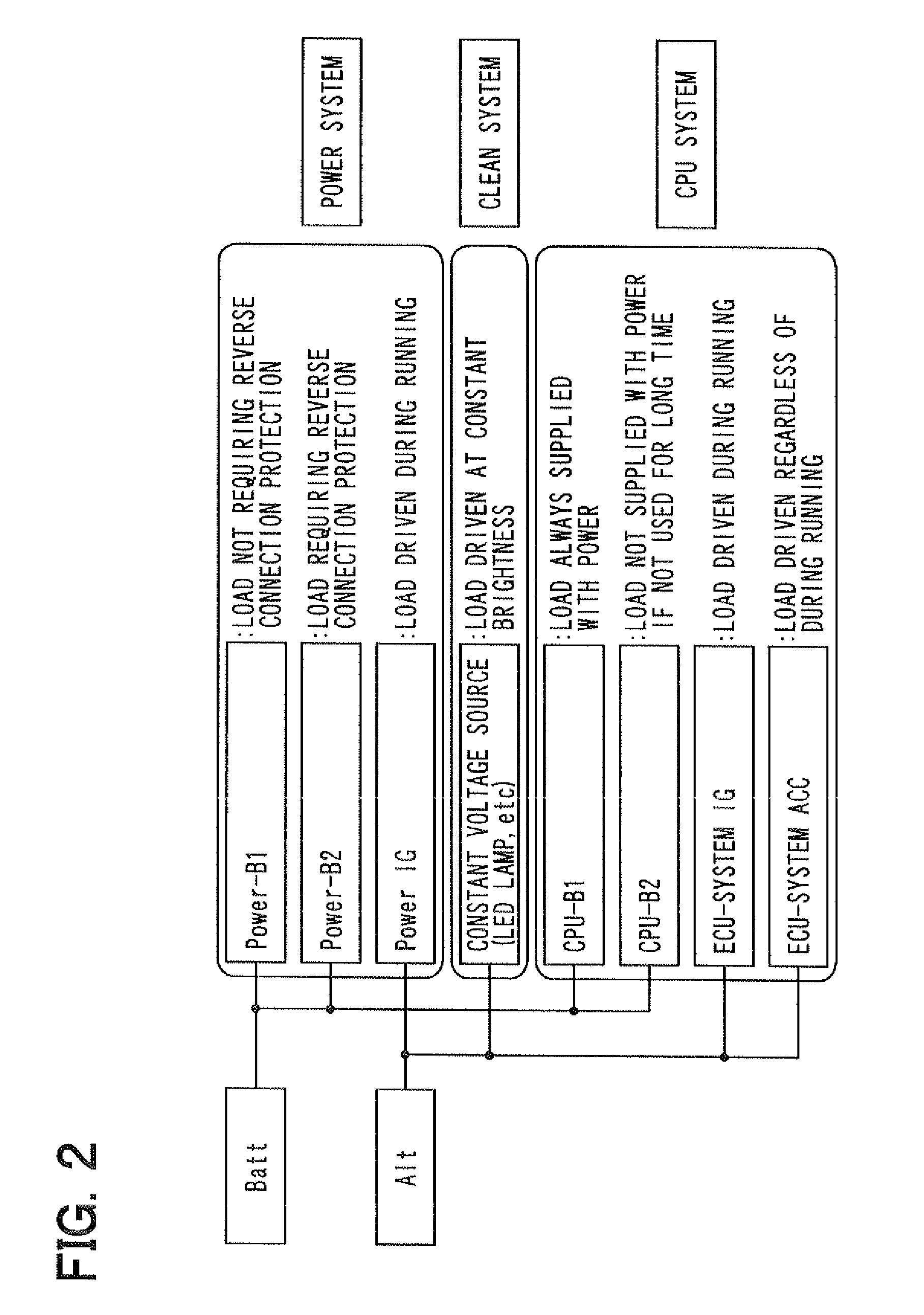
[0015]An embodiment of the present invention is described below with reference to FIGS. 1 and 2. FIG. 1 illustrates a circuit diagram of a vehicular power supply circuit according to the embodiment of the present invention. FIG. 2 is a brief diagram illustrating loads connected to systematically-separated power lines of the vehicular power supply circuit.

[0016]In the vehicular power supply circuit shown in FIG. 1, a main power line connected to a battery 1 is systematically separated into sub-power lines based on characteristics of loads, such as ECUs and power loads, to be connected. FIG. 2 conceptually shows how to separate the main power line into the sub-power lines.

[0017]Specifically, as shown in FIG. 1, the main power line is separated into a power line 2 (as a first power line) and a power line 4 (as a second power line). The power line 2 serves as a power line of a battery system that is connected directly to the battery 1, and the power line 4 serves as a power line of an i...


PUM


Abstract

A vehicular power supply circuit for supplying power to loads from a battery to drive the loads includes a power line and noise protection circuits. The power line is connected to the loads and systematically separated into multiple power lines based on characteristics of the loads to be connected. Each noise protection circuit is provided to a corresponding power line on the upstream side of the loads connected to the corresponding power line to serve as a common noise protection circuit for the loads connected to the corresponding power line.

Description

CROSS REFERENCE TO RELATED APPLICATION[0001]This application is based on and incorporates herein by reference Japanese Patent Application No. 2009-263850 filed on Nov. 19, 2009.FIELD OF THE INVENTION[0002]The present invention relates to a vehicular power supply circuit for supplying electrical power to electrical loads of a vehicle.BACKGROUND OF THE INVENTION[0003]As disclosed in, for example, JP 6-32186 A, a conventional power supply circuit for a vehicle has two main power supply systems, one of which is a battery system, and the other of which is an ignition (IG) system. The battery system is connected directly to a battery so that power can be supplied to the battery system regardless of whether an IG switch of a vehicle is ON or OFF. On the other hand, the IG system is supplied with power only when the IG switch is ON. For example, a headlamp and an electronic control unit (ECU) for controlling a keyless entry apparatus that performs door lock control are connected to a power ...

Claims


Application Information

Patent Timeline
Patent Type & Authority Applications(United States)
IPC IPC(8): H02G3/00
CPCB60L2270/147B60R16/033Y02T10/7077Y02T10/70B60L11/14B60L2270/142B60L1/003B60L50/16Y02T10/7072
Inventor MORITA, MANABUSATO, KOICHIODA, MOTOHARUTAKAGI, NOBUTOMOSUGANUMA, HIDEOITO, JIRO
Owner ANDEN CORP
Why Eureka
Try Eureka