
Transformer and method of making the same

a transformer and transformer technology, applied in the field of transformers, can solve the problems of large exposed portion, variable insulating results, unstable, etc., and achieve the effect of more firmly secured electrical safety of the transformer

Active Publication Date: 2011-05-19
DELTA ELECTRONICS INC
View PDF4 Cites 18 Cited by
  • Summary
  • Abstract
  • Description
  • Claims
  • Application Information

AI Technical Summary

Benefits of technology

[0008]It is an object of an embodiment of the present invention to provide a transformer and a method of making the same in which the transformer has an improved insulator to separate the transformer, and especially the magnetic core, from other components so that the electrical safety of the transformer is capable to be more firmly secured.
[0009]It is another object of an embodiment of the present invention to provide a transformer and a method of making the same in which the transformer has an improved insulating case to protect the magnetic core from short circuit risk in collision accidents so that the stability of the electrical safety of the transformer is capable to be increased.
[0010]It is another object of an embodiment of the present invention to provide a transformer and a method of making the same in which the transformer is of simple construction and has an improved insulating slipcase engaged with the bobbin so that the fabrication work of the transformer is easier and the costs are lower.

Problems solved by technology

The most pressing problems facing the industry will be the safety issue, especially when the design trend of electronic devices tends to reduce the device size and cost.
Nevertheless, the insulating results can vary and be unstable.
Especially, the exposed portion is quite huge and the insulating tape is required to be attached and secured by hand in normal cases.
Even though the tape has been attached precisely right to the required portion, the security of the tape can fail at any time resulting from inadvertently move or touch conducted by the worker during the assembly.
Besides, the security of the insulting tape may come to be unstable over time.
Also, it appears that the conventional transformers may not be suitable for the use of the electronic devices which are under the high density design.
Likewise, the traditional way has shown that more risks might arise while such transformers are for the use with a portable electronic device.
The collision accidents may cause the components inside becoming, for example, loose or distortion, and may directly result in a breaking of the insulating which may lead to serious electrical safety issues.

Method used


Image

  • Transformer and method of making the same
  • Transformer and method of making the same
  • Transformer and method of making the same

Examples


Embodiment Construction

[0019]The present invention will now be described more specifically with reference to the following embodiments. It is to be noted that the following descriptions of preferred embodiments of this invention are presented herein for purpose of illustration and description only. It is not intended to be exhaustive or to be limited to the precise form disclosed.

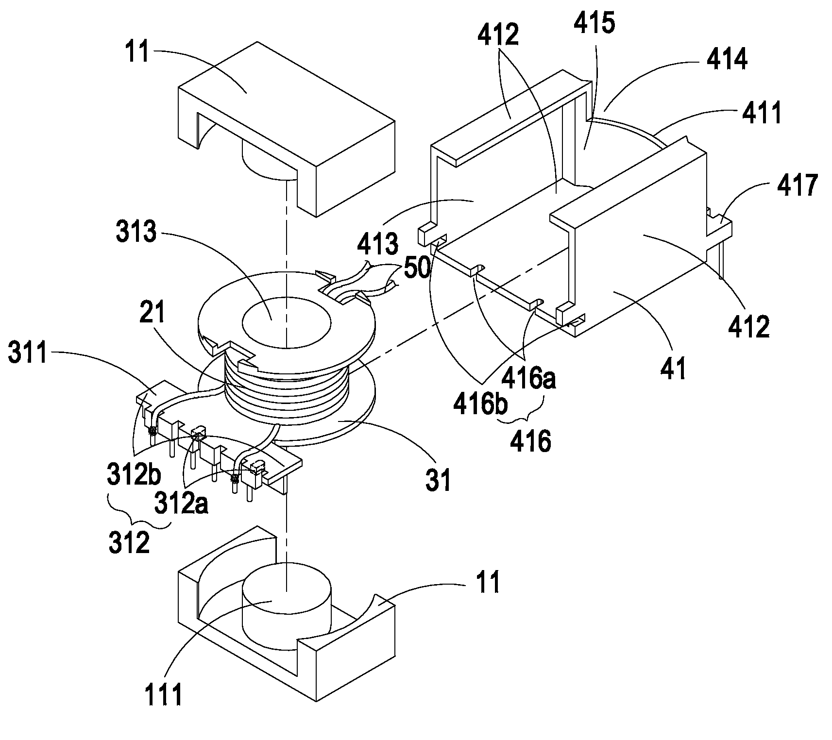
[0020]FIG. 3 and FIG. 4 respectively illustrate an exploded and an assembled view schematically showing a transformer according to one embodiment of the invention. In this embodiment, the transformer 10 comprises a magnetic core 11, a winding coil 21 with a primary winding coil and a secondary winding coil, a bobbin 31 with a primary input port 311 and a bobbin connecting member 312, and an insulating slipcase 41. The bobbin 31 is mounted by the winding coil 21. The insulating slipcase 41 includes a first opening 413 to receive the magnetic core 11, the winding coil 21 and the bobbin 31, a first side wall 411, a second side wall ...


PUM

PropertyMeasurementUnit
Magnetismaaaaaaaaaa
aaaaaaaaaa

Abstract

A transformer and a method of manufacturing the same are disclosed. The transformer comprises a magnetic core, a winding coil with a primary winding coil and a secondary winding coil, a bobbin with a primary input port and a bobbin connecting member, and an insulating slipcase. The bobbin is mounted by the winding coil. The insulating slipcase includes a first opening to receive the magnetic core, the winding coil and the bobbin, and includes a first side wall, a second side wall with a slipcase connecting member which is engaged with the bobbin connecting member, and a secondary output port for dealing with the output of the transformer. The first side wall is opposite to the first opening and has a second opening for the output of the secondary winding coil.

Description

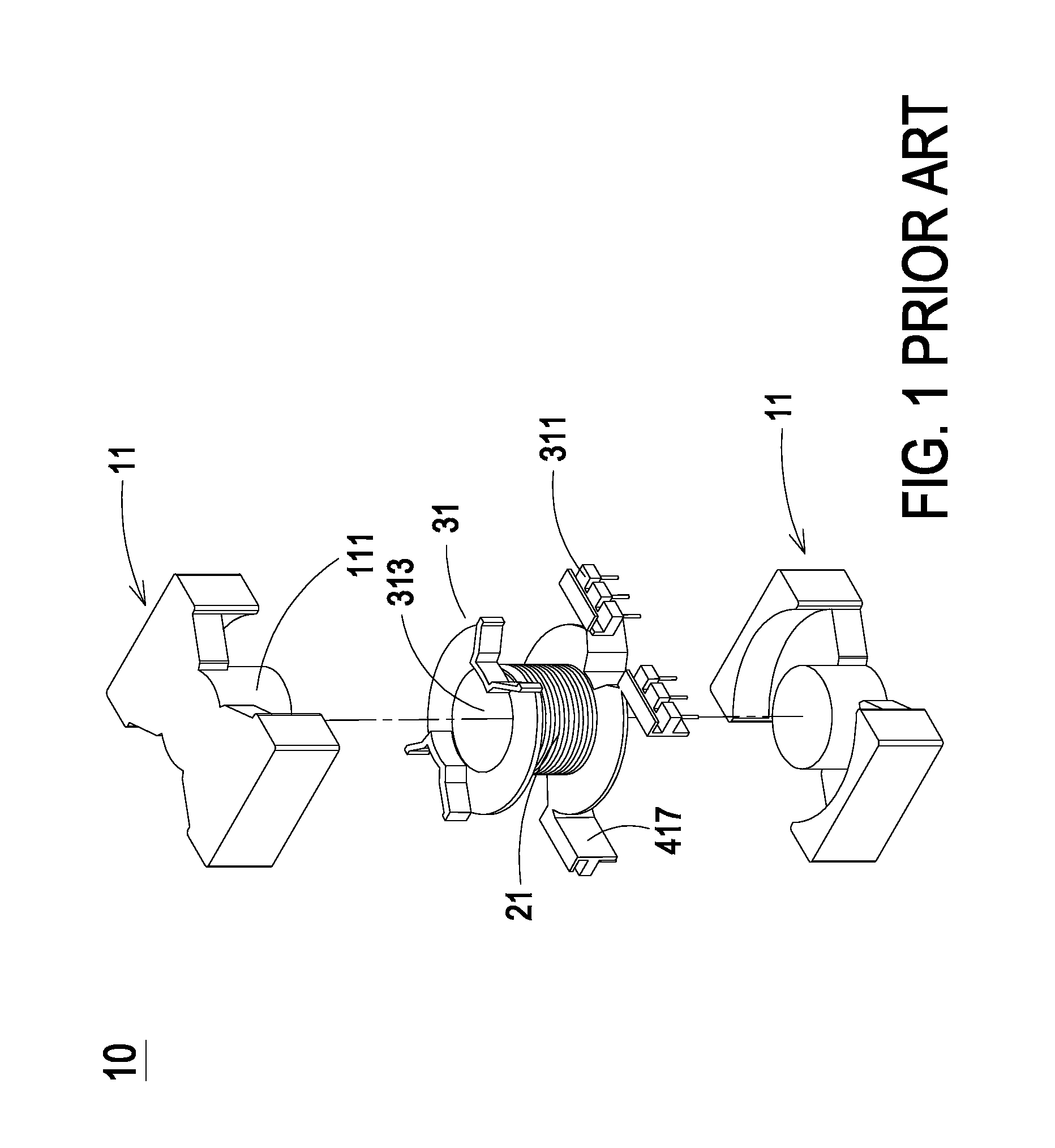
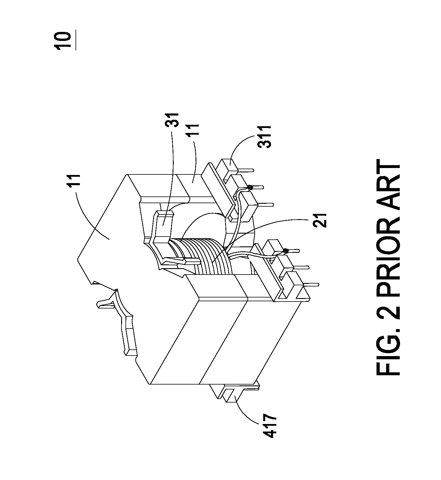
FIELD OF THE INVENTION[0001]The present invention relates to a transformer and a method of making the same; and more particularly to a transformer with an increased electrical insulation, and a method of making the same.BACKGROUND OF THE INVENTION[0002]A transformer is a key component for a wild variety of electronic devices. The most pressing problems facing the industry will be the safety issue, especially when the design trend of electronic devices tends to reduce the device size and cost. As a matter of fact, the components inside various electronic devices are placed in high density nowadays.[0003]In general, a conventional transformer would comprise a winding coil, a magnetic core, and a bobbin mounted by the winding coil. As shown in FIGS. 1 and 2, they are an exploded view and an assembled view of a conventional transformer. The transformer 10 is constructed by the combination of the magnetic core 11 and the bobbin 31 which is mounted by the winding coil 21. As illustrated, ...

Claims


Application Information

Patent Timeline
IPC IPC(8): H01F27/02H01F41/06
CPCH01F27/02H01F27/06Y10T29/49071H01F2027/065H01F27/306
Inventor LIAO, KAO-TSAICHUNG, HIS-KUOPENG, MING-SHIANHUNG, YU-LIANG
Owner DELTA ELECTRONICS INC
Learn More