Vacuum fluorescent display driving apparatus

Active Publication Date: 2011-05-19
LAPIS SEMICON CO LTD
View PDF4 Cites 6 Cited by
  • Summary
  • Abstract
  • Description
  • Claims
  • Application Information

AI Technical Summary

Benefits of technology

[0010]The present invention provides a vacuum fluorescent display driving apparatus and a vacuum fluorescent display driving method that may prevent generation of excessive load on power lines employed in driving without causing an increase in size of the apparatus.

Problems solved by technology

Accordingly, as the number increases of grid electrodes to which power is to be supplied simultaneously, excessive current flows in the power lines of the grid driver employed for driving.
This results in a deterioration and / or melting and breaking of the power lines.
Whilst the above can be rectified by increasing the thickness of the power lines, if the thickness of the power lines is simply increased this leads to a corresponding increase in size of the apparatus.

Method used


Image

  • Vacuum fluorescent display driving apparatus
  • Vacuum fluorescent display driving apparatus
  • Vacuum fluorescent display driving apparatus

Examples


first exemplary embodiment

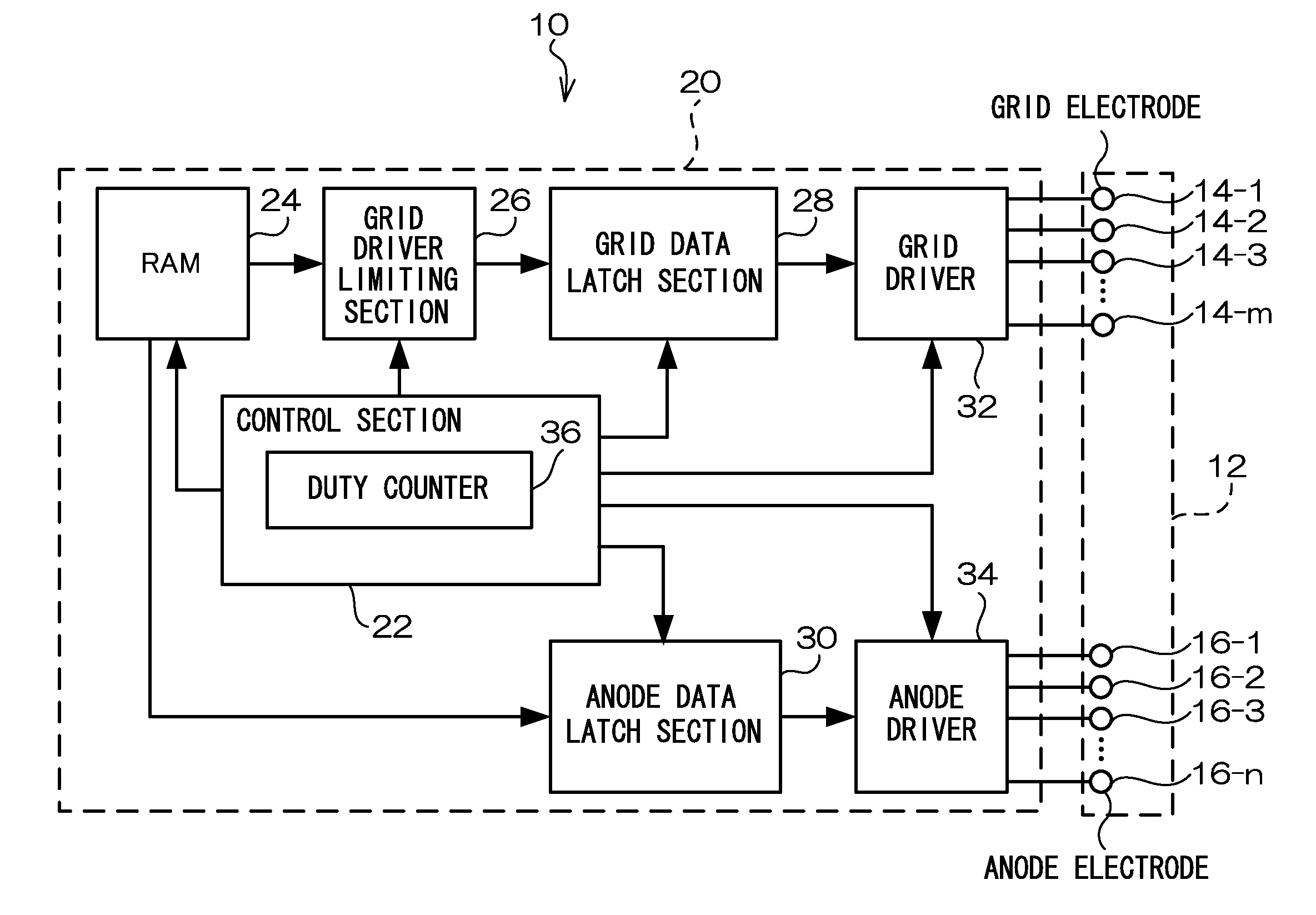
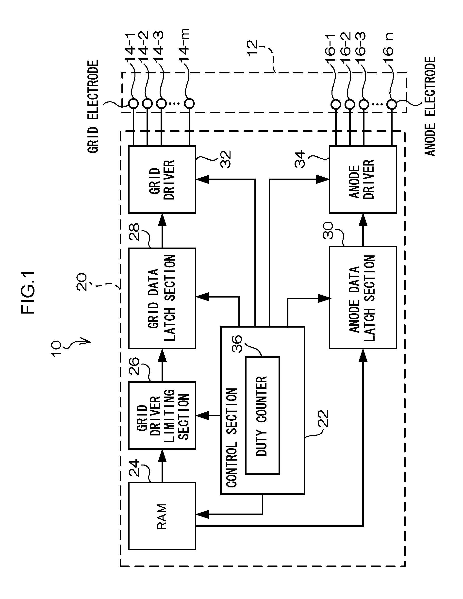
[0033]FIG. 1 shows a configuration of a vacuum fluorescent display apparatus (referred to below as “display apparatus”) 10 according to a present exemplary embodiment.

[0034]As shown in FIG. 1, the display apparatus 10 according to the present exemplary embodiment is configured including a fluorescent display section 12 and a controller driver 20.

[0035]The fluorescent display section 12 according to the present exemplary embodiment includes grid electrodes 14-1 to 14-m (wherein “m” is the number of grid electrodes) connected to corresponding respective grids, and anode electrodes 16-1 to 16-n (wherein“n” is the number of anode electrodes) connected to corresponding respective anodes. In the explanation below, reference will be made with suffixes 1 to m applied to the reference numeral representing the grid electrode when discrimination is made between each of the grid electrodes 14-1 to 14-m, as above. However, reference will be made to grid electrodes 14 when no discrimination is ma...

second exemplary embodiment

[0089]In the present second exemplary embodiment, configuration is made such that sum of the number of grid electrodes 14 and the number of anode electrodes 16 to which voltage is simultaneously applied is less than a predetermined threshold value.

[0090]FIG. 6 is a diagram showing a circuit configuration of a grid driver limiting section 26 and an anode driver limiting section 26′ according to the second exemplary embodiment. For configuration similar to that of the grid driver limiting section 26 of the first exemplary embodiment, the same reference numerals are appended and explanation thereof is omitted. As an example, explanation follows of a case where the number of grid electrodes 14 is 10, and the number of anode electrodes 16 is 16.

[0091]The anode driver limiting section 26′ includes a selector circuit 61′ connected to output terminals of the RAM 24 outputting anode data through connection lines (referred to below as “anode data lines”) 90-1 to 90-16, and a latch section 52′...


PUM


Abstract

The present invention provides a vacuum fluorescent display driving apparatus and a vacuum fluorescent display driving method that may prevent generation of excessive load on power lines employed in driving, without causing an increase in size of the apparatus. The vacuum fluorescent display driving apparatus of the present invention includes, a grid driver that applies a driving voltage to plural grid electrodes respectively provided in the vacuum fluorescent display, and a grid driver limiting section that performs limitation on the number of grid electrodes to which voltage is applied simultaneously by the grid driver, to less than a predetermined first threshold value.

Description

CROSS-REFERENCE TO RELATED APPLICATION[0001]This application claims priority under 35 USC 119 from Japanese Patent Application No. 2009-261136 filed on Nov. 16, 2009, the disclosure of which is incorporated by reference herein.BACKGROUND OF THE INVENTION[0002]1. Field of the Invention[0003]The present invention relates to a vacuum fluorescent display driving apparatus. The present invention particularly relates to a driving apparatus employed with a vacuum fluorescent display having plural grid electrodes and anode electrodes.[0004]2. Description of the Related Art[0005]Vacuum fluorescent displays are employed as display elements for displaying an image. Vacuum fluorescent displays discharge electrons from a filament, and accelerate the discharged electrons by selectively applying voltage to grids and anodes, such that the electrons are irradiated onto fluorescent body provided to an anode.[0006]A controller driver for vacuum fluorescent displays is described in Japanese Patent Appl...

Claims


Application Information

Patent Timeline
IPC IPC(8): G09G3/22G06F3/038
CPCG09G3/06
Inventor YUSA, ATSUSHI
Owner LAPIS SEMICON CO LTD
Why Eureka
Try Eureka