Apparatus and method for draining stored power

a technology of stored power and apparatus, applied in the direction of overvoltage protection resistors, emergency protective arrangements for limiting excess voltage/current, relays, etc., to achieve the effect of reducing electromagnetic interference and increasing the efficiency of the power supply circui

Inactive Publication Date: 2011-05-19
LIEN CHANG ELECTRONICS ENTERPRISE
View PDF1 Cites 8 Cited by
  • Summary
  • Abstract
  • Description
  • Claims
  • Application Information

AI Technical Summary

Benefits of technology

The present invention provides a way to drain the power stored in the capacitors of an EMI filter circuit when the power supply circuit is not operating. This is done to increase the efficiency of the power supply circuit. The apparatus includes an open-circuit resistor that has very high electrical resistance to stop draining the stored power of the EMI filter circuit when the power supply circuit is working.

Problems solved by technology

The technical problem addressed by this patent is how to safely and stably eliminate electromagnetic interference from circuits used for power supply while also preventing unstable or excessive power consumption caused by a continuous use of a bleeper during operation.

Method used


Image

  • Apparatus and method for draining stored power
  • Apparatus and method for draining stored power
  • Apparatus and method for draining stored power

Examples


Embodiment Construction

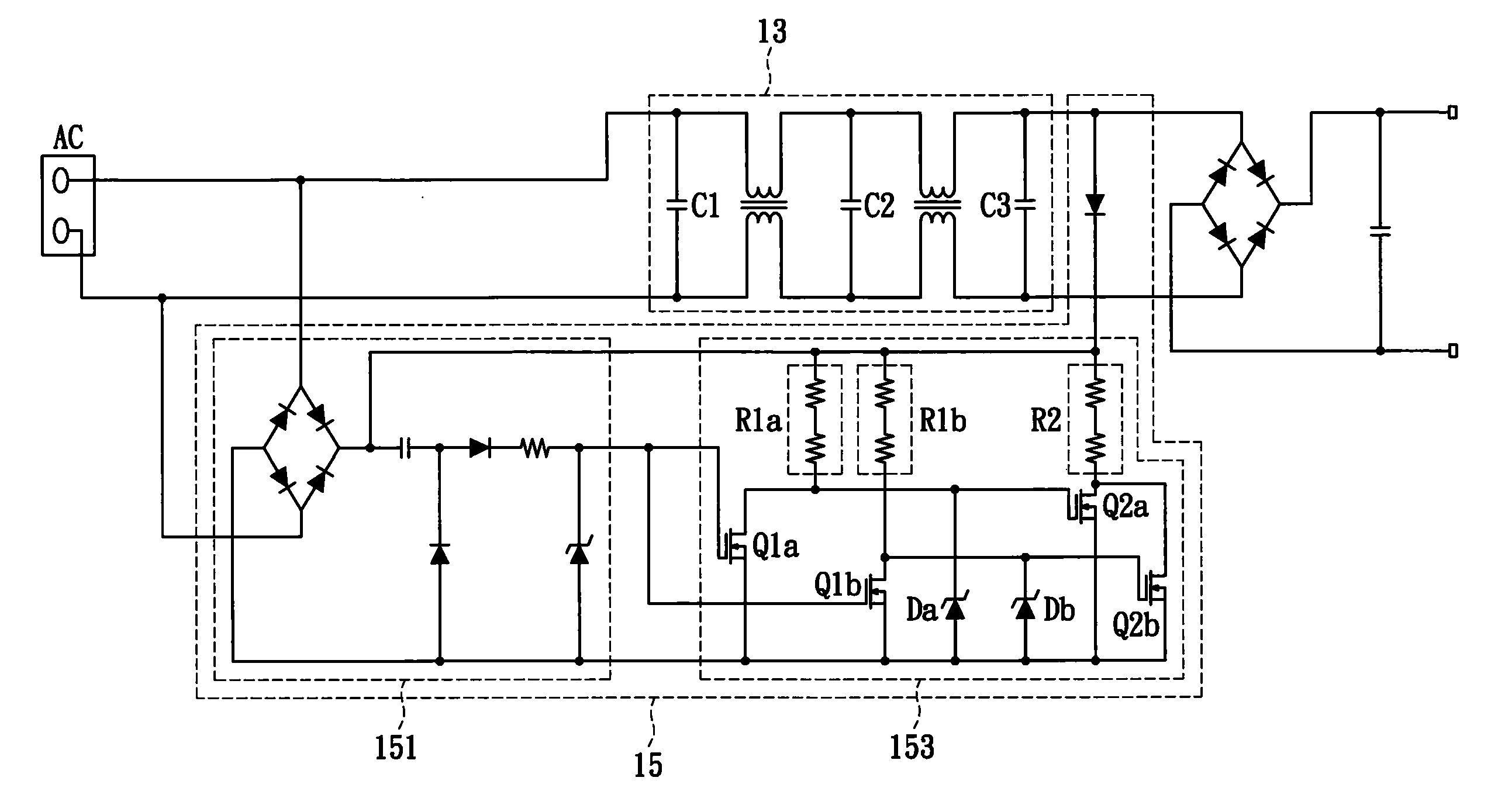
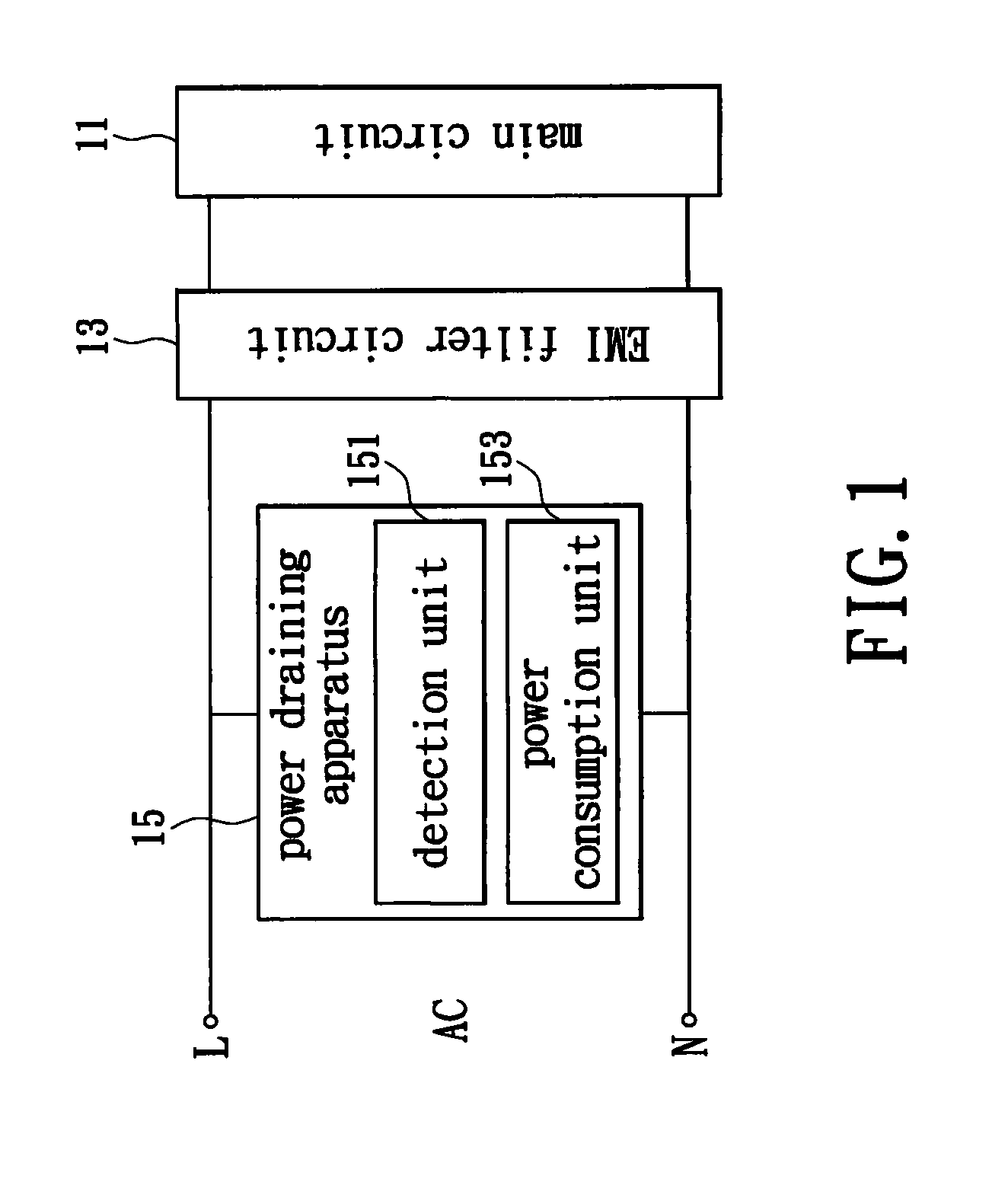
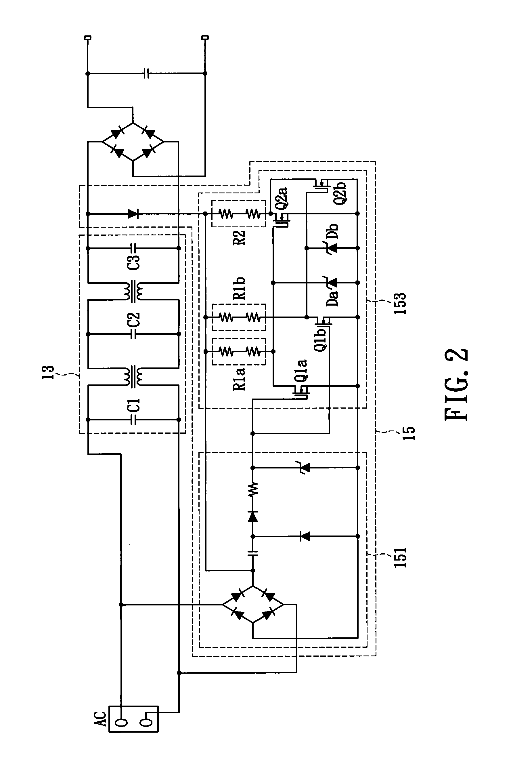
[0017]Please refer to FIG. 1, which is a block diagram of an embodiment of a power supply circuit. The power supply circuit includes a main circuit 11, an EMI filter circuit 13, and a power draining apparatus 15. Wherein the EMI filter circuit 13 is coupled with the main circuit 11 for eliminating electromagnetic interference. The power draining apparatus 15 is coupled with the EMI filter circuit 13 for draining the power stored in at least one capacitor of the EMI filter circuit 13.

[0018]The power draining apparatus 15 has a detection unit 151 and a power consumption unit 153, in which the detection unit 151 and the power consumption unit 153 are coupled with each other. The detection unit 151 is for detecting an alternating current power AC which is inputted into the EMI filter circuit 13 through an input end. After that, operation status of the power supply circuit is determined according to the detection result, and a detection signal is then generated and transmitted to the pow...


PUM


Abstract

Apparatus and method for draining stored power are disclosed, which the apparatus and method are applied to an EMI filter circuit for draining power. When the power supply circuit is not working, the apparatus provides a bleeder resistor to drain the power stored in the capacitors of the EMI filter circuit. On the other hand, when the power supply circuit is working, the apparatus provides an open-circuit resistor which has extremely large electrical resistance in order to stop draining power. Thus, the apparatus for draining stored power will not cause extra power waste.

Description


Claims


Application Information

Patent Timeline
Owner LIEN CHANG ELECTRONICS ENTERPRISE
Why Eureka
Try Eureka