Optical connector, and assembling method of optical connector

a technology of optical connectors and connectors, applied in the field of optical connectors, can solve the problems of cumbersome work such as the attachment of the boot and the protecting tube, troublesome fiber breakage, and take some time, and achieve the effect of reducing the number of connections and parts, and facilitating and stably assembling

Inactive Publication Date: 2011-05-19
SUMITOMO ELECTRIC IND LTD +1
View PDF6 Cites 16 Cited by
  • Summary
  • Abstract
  • Description
  • Claims
  • Application Information

AI Technical Summary

Benefits of technology

[0006]An object of the present invention is therefore to provide an optical connector capable of readily protecting a coated fiber, and an assembling method of the optical connector improved in workability during assembly of the optical connector at a job site.
[0046]This assembling method of the optical connector reduces the number of connections and the number of parts and permits a worker to readily and stably assemble at a job site, the optical connector in the simple configuration which prevents the coated fiber exposed out of the cable jacket, from being subject to an excessive force such as a bending force from the outside during a work.

Problems solved by technology

In the above-described optical connector, the coated fiber is led out from the rear end face of the mechanical splice and the coated fiber can be subject to an excessive force such as a bending force from the outside during a work, which could result in causing trouble of breakage of the fiber or the like.
However, works such as attachment of the boot and the protecting tube are cumbersome and take some time.

Method used


Image

  • Optical connector, and assembling method of optical connector
  • Optical connector, and assembling method of optical connector
  • Optical connector, and assembling method of optical connector

Examples


first embodiment

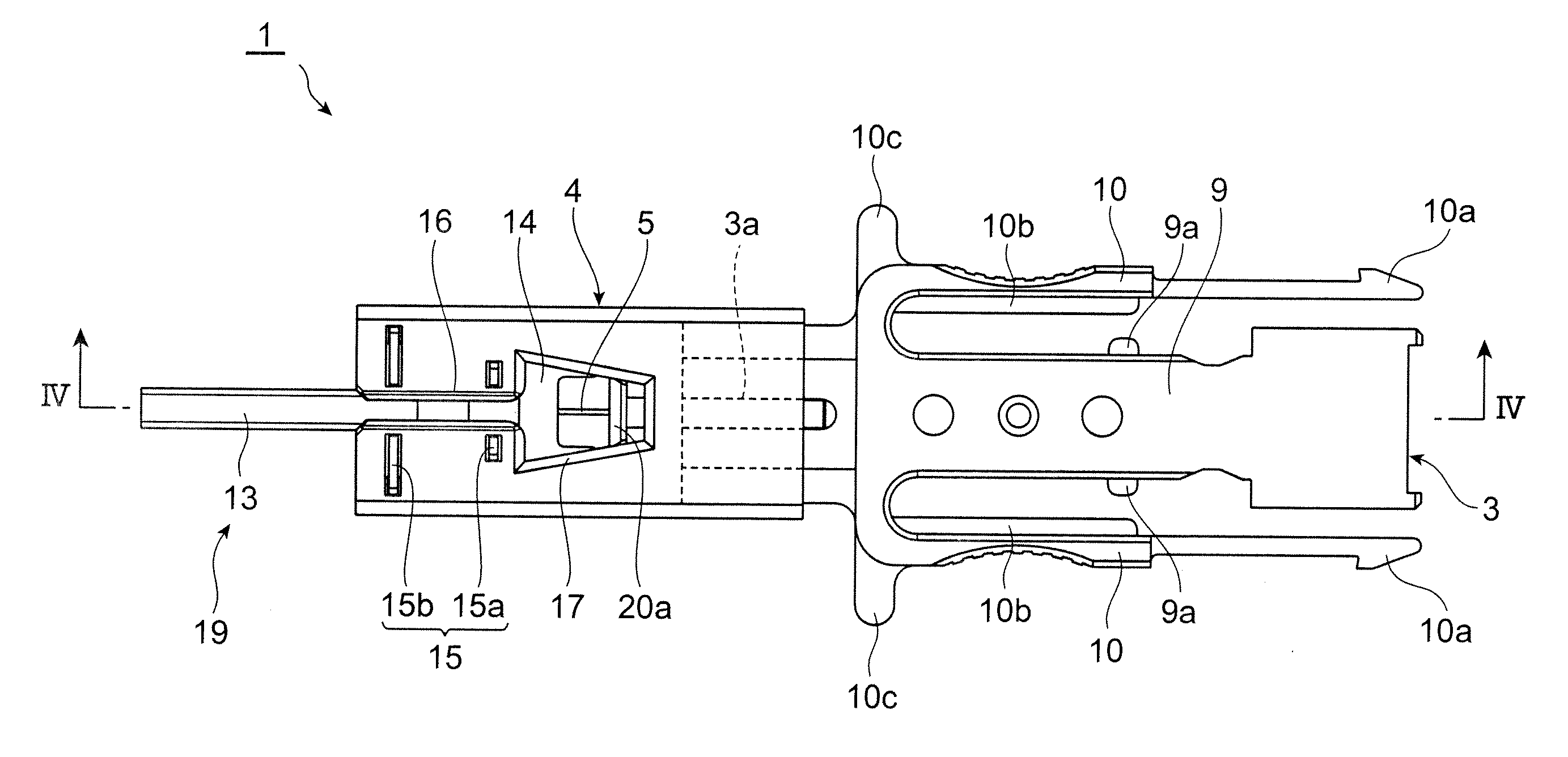
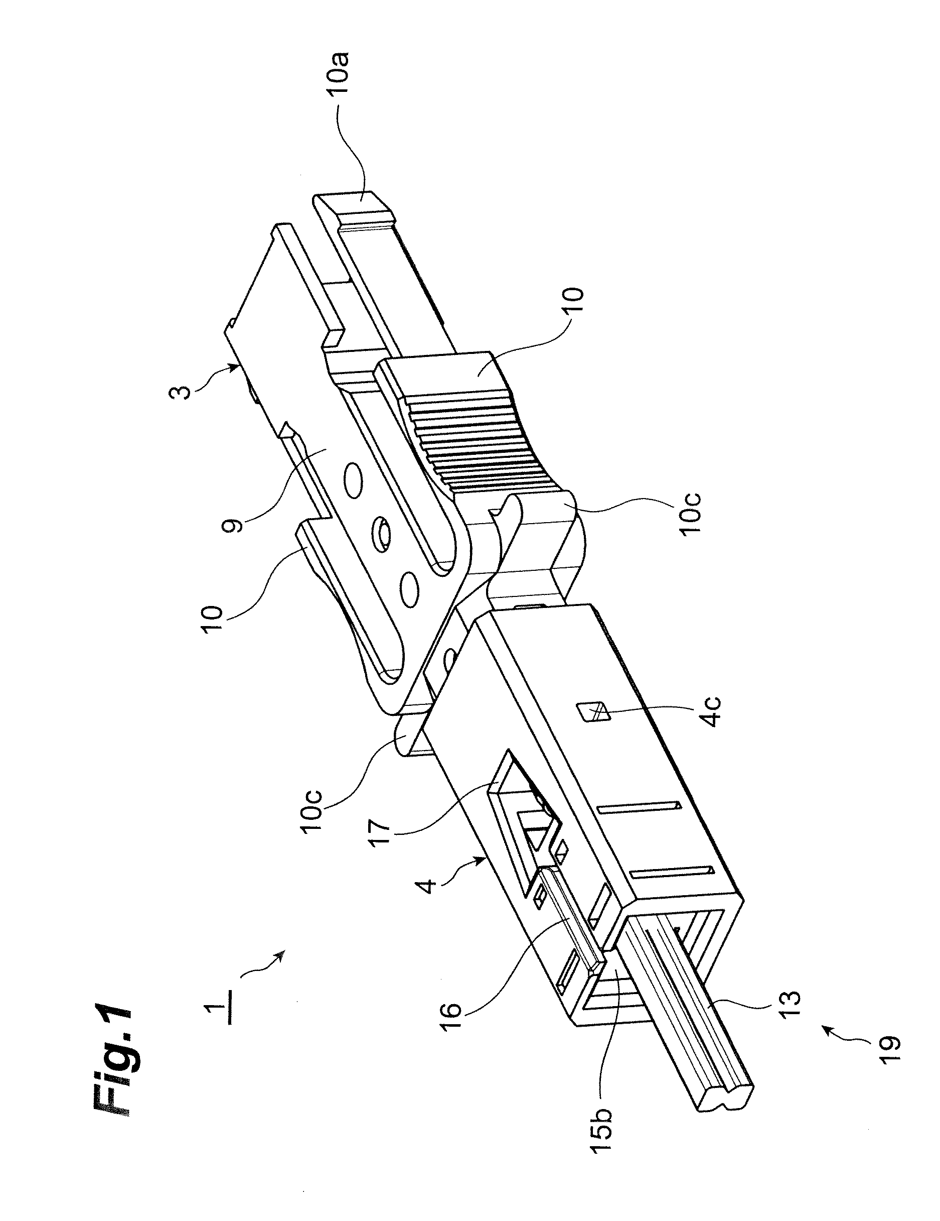
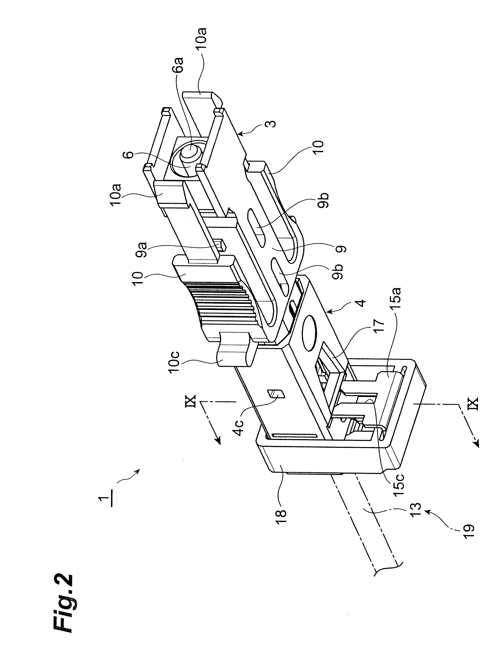
[0080]FIG. 1 is a perspective view of a male optical connector according to the first embodiment of the present invention, FIG. 2 a perspective view of the lower side of the male optical connector (before insertion of a clip) shown in FIG. 1, FIGS. 3 to 5 views showing the male optical connector, FIG. 6 a perspective view of a coupling member shown in FIG. 5, FIG. 7 a perspective view of a spring push shown in FIG. 5, FIGS. 8 and 9 views showing a jacket holder shown in FIG. 5, and FIG. 18 a transverse sectional view of an indoor cable. In the description hereinafter, terms indicating directions will be based on the state shown in FIG. 1. Specifically, a direction in which a jacket fixture is located relative to an outer housing is defined as “back.”

[0081]The optical connector of the present embodiment is an in-situ assembling type single-fiber optical connector having a mechanical splice structure and being suitable for assembly at a job site, and is used for connection of an optic...

second embodiment

[0159]Next, a male optical connector according to the second embodiment of the present invention will be described with reference to FIGS. 19 to 23. FIG. 19 is a perspective view of the male optical connector in a closed lid state (before attachment of an optical cable), and FIGS. 20 to 23 are views showing the male optical connector of FIG. 19 in an open lid state. This male optical connector 31 of the second embodiment is different from the male optical connector 1 of the first embodiment in that the jacket fixture 4 shown in FIG. 1 is replaced by a jacket fixture 32 shown in FIGS. 19-23 and in that the jacket holder 14 shown in FIG. 5 is replaced with a jacket holder 37 shown in FIG. 21, without the clip 15 shown in FIG. 5.

[0160]Specifically, as shown in FIGS. 19-23, the jacket fixture 32 is provided with a jacket fixture body 33 coupled to the mechanical splice through a coupling member having much the same function as in the first embodiment, a first movable portion 35 and a se...


PUM


Abstract

An optical connector according to an embodiment of the present invention comprises (a) a ferrule incorporating a short fiber; (b) a mechanical splice having a holding part and a fixing part, and adapted so that the fixing part mechanically fixes the short fiber extending from the ferrule held by the holding part, and an optical fiber in an optical cable to butt the short fiber; (c) an outer housing having a housing part in which the mechanical splice is located, and a pair of flexible arms located on both sides of the housing part, the pair of arms each being provided with a locking claw at a tip; and (d) a jacket fixture for fixing a cable jacket, the jacket fixture being coupled to the mechanical splice so that the cable jacket is inserted therein.

Description

RELATED APPLICATIONS[0001]This application is a Divisional of U.S. patent application Ser. No. 11 / 660,539, filed on Aug. 30, 2007, which is a U.S. National Phase under 35 U.S.C. §371 of International Application No. PCT / JP2005 / 015638, filed on Aug. 29, 2005, which in turn claims the benefit of Japanese Application No. 2004-259380, filed on Sep. 7, 2004, the disclosures of which Applications are incorporated by reference herein.TECHNICAL FIELD[0002]The present invention relates to an optical connector to be suitably connected to an optical cable of a tight structure, and to an assembling method of the optical connector.BACKGROUND ART[0003]For example, an optical cable such as a drop cable or an indoor cable is a cable in which a coated optical fiber and tension members are covered by a jacket (sheath), and has a so-called tight structure in which the coated optical fiber and tension members are attached tightly to the cable jacket.[0004]A conventional optical connector to be connecte...

Claims


Application Information

Patent Timeline
Patent Type & Authority Applications(United States)
IPC IPC(8): G02B6/38
CPCG02B6/3829G02B6/3893G02B6/3887G02B6/3846G02B6/38875G02B6/36G02B6/38
Inventor NISHIOKA, DAIZOOHTSUKA, KENICHIROSAITO, KAZUHITOTAMEKUNI, YOSHIKYOYOKOMACHI, YUKIHIROEMA, TUNETAKANAKAZAWA, KENICHIHOSHINO, YASUHIKO
Owner SUMITOMO ELECTRIC IND LTD
Why Eureka
Try Eureka