Electric water pump

a technology of electric water pump and water pump body, which is applied in the direction of piston pump, positive displacement liquid engine, liquid fuel engine, etc., can solve the problems of increasing fuel consumption of vehicles and increasing fuel consumption, and achieve the effect of preventing interference and collision

Active Publication Date: 2011-05-19
HYUNDAI MOTOR CO LTD +3
View PDF68 Cites 9 Cited by
  • Summary
  • Abstract
  • Description
  • Claims
  • Application Information

AI Technical Summary

Benefits of technology

[0010]Various aspects of the present invention are directed to provide an electric water pump having advantages of improved performance and durability.
[0014]A first bearing may be disposed between the shaft and the front surface of the body in the rotor chamber in order to reduce rotational friction of the shaft, wherein the rotor is formed in an unsymmetrical shape so as to generate thrust toward the front surface of the body, wherein a cup is mounted between the first bearing and the rotor on the shaft in order to prevent interference and collision of the shaft and the first bearing by the thrust, and a thrust ring is mounted between the cup and the first bearing for smooth rotation of the shaft, and wherein the cup is made of a rubber material and the thrust ring is made of a ceramic material.
[0017]A second bearing may be disposed between a rear end portion of the shaft and the front surface of the driver case in order to reduce a rotational friction of the shaft wherein the second bearing is disposed between a stepped portion of the shaft at a rear side of the shaft and the front surface of the driver case in order to reduce the rotational friction of the shaft.
[0023]A first bearing may be disposed between the shaft and the front surface of the body in the rotor chamber and a cup is mounted between the first bearing and the rotor cover on the shaft in order to prevent interference and collision of the shaft and the first bearing by the thrust, and a thrust ring is mounted between the cup and the first bearing for smooth rotation of the shaft, wherein the cup is made of a rubber material and the thrust ring is made of a ceramic material.

Problems solved by technology

However, if the engine speed is increased, fuel consumption of a vehicle also increases.

Method used


Image

  • Electric water pump
  • Electric water pump
  • Electric water pump

Examples


Embodiment Construction

[0029]Reference will now be made in detail to various embodiments of the present invention(s), examples of which are illustrated in the accompanying drawings and described below. While the invention(s) will be described in conjunction with exemplary embodiments, it will be understood that present description is not intended to limit the invention(s) to those exemplary embodiments. On the contrary, the invention(s) is / are intended to cover not only the exemplary embodiments, but also various alternatives, modifications, equivalents and other embodiments, which may be included within the spirit and scope of the invention as defined by the appended claims.

[0030]An exemplary embodiment of the present invention will hereinafter be described in detail with reference to the accompanying drawings.

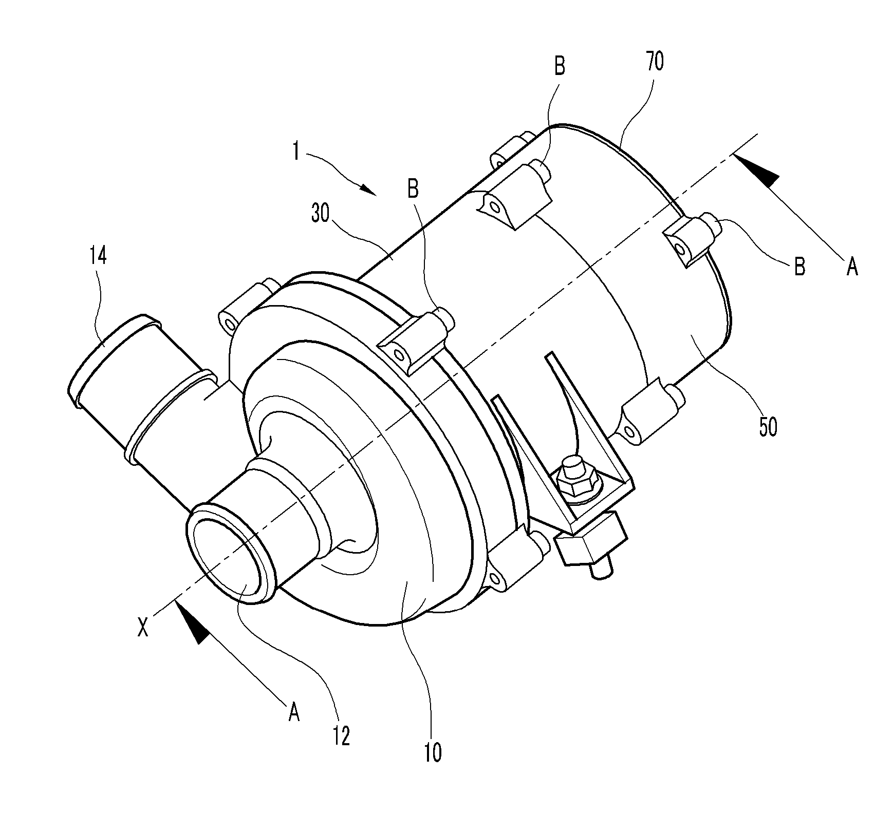
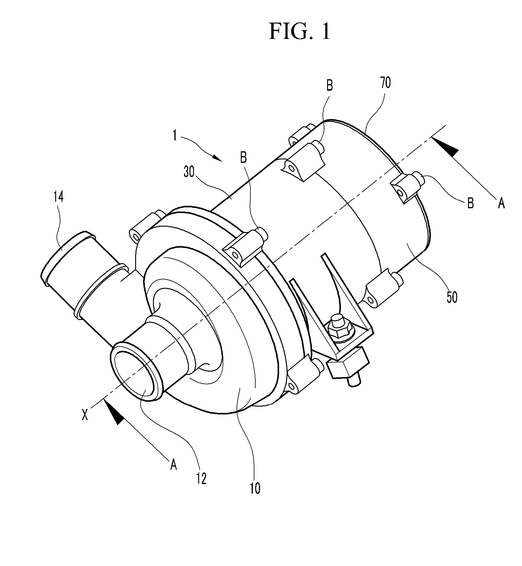
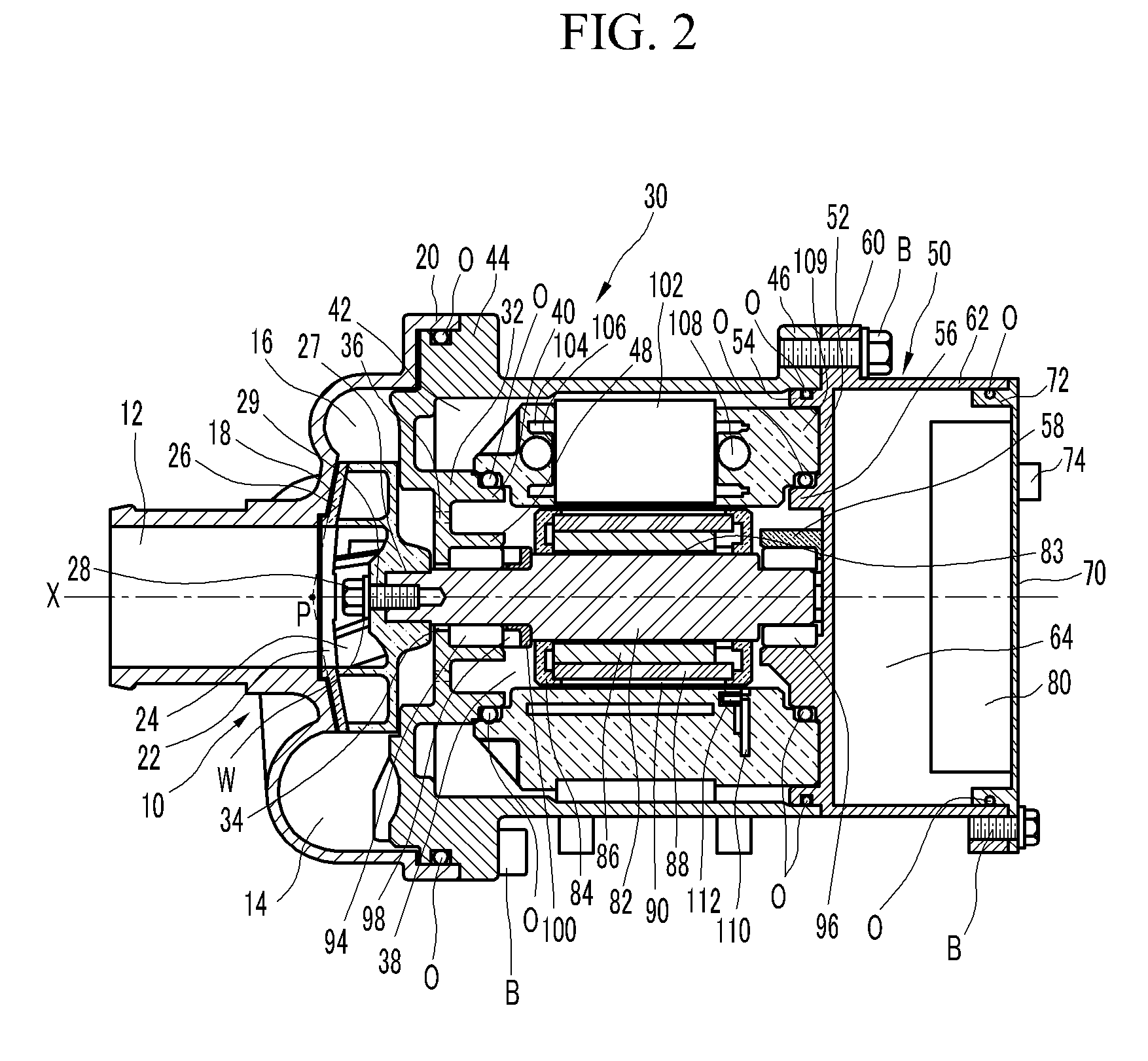
[0031]FIG. 1 is a perspective view of an electric water pump according to an exemplary embodiment of the present invention, and FIG. 2 is a cross-sectional view taken along the line A-A in FIG. 1.

[...


PUM


Abstract

The present invention relates to an electric water pump having improved performance and durability. The electric water pump may include a stator generating a magnetic field according to a control signal, a rotor rotated by the magnetic field, a pump cover having an inlet and an outlet, a body having a front surface forming a volute chamber, a stator chamber, and a rotor chamber, the stator mounted in the stator chamber and the rotor mounted in the rotor chamber, a shaft having a central axis, fixed to the rotor and mounted in the rotor chamber, and an impeller fixed to the shaft so as to rotate together with the shaft, pressurizing the coolant having flowed in through the inlet, and mounted in the volute chamber, wherein the rotor chamber is fluidly connected to the volute chamber, and the stator chamber is fluidly closed and sealed from the rotor chamber.

Description

CROSS-REFERENCE TO RELATED APPLICATION[0001]The present application claims priority to Korean Patent Application No. 10-2009-0112235 filed on Nov. 19, 2009, the entire contents of which is incorporated herein for all purposes by this reference.BACKGROUND OF THE INVENTION[0002]1. Field of the Invention[0003]The present invention relates to an electric water pump. More particularly, the present invention relates to an electric water pump having improved performance and durability.[0004]2. Description of Related Art[0005]Generally, a water pump circulates coolant to an engine and a heater in order to cool the engine and heat a cabin. The coolant flowing out from the water pump circulates through and exchanges heat with the engine, the heater, or the radiator, and flows back in the water pump. Such a water pump is largely divided into a mechanical water pump and an electric water pump.[0006]The mechanical water pump is connected to a pulley fixed to a crankshaft of the engine and is dri...

Claims


Application Information

Patent Timeline
Patent Type & Authority Applications(United States)
IPC IPC(8): F04B35/04
CPCF04D13/0633F04D13/064F04D13/0686F01P5/12H02K11/0073H02K5/08H02K5/12H02K7/14H02K9/197H02K29/08H02K11/33F01P5/10F04D13/06F04D29/046H02K15/02
Inventor YI, JEAWOONGLEE, SEUNG YONGKIM, GYUHWANKIM, YUN SEOKPARK, YONG SUNOH, TAE-SUNGKIM, KYUNG-HWANLEE, JONG-HOONLEE, KWANG-HO
Owner HYUNDAI MOTOR CO LTD
Why Eureka
Try Eureka