Catalyst coated electrolyte membrane, fuel cell including the same, method of preparing the catalyst coated electrolyte membrane

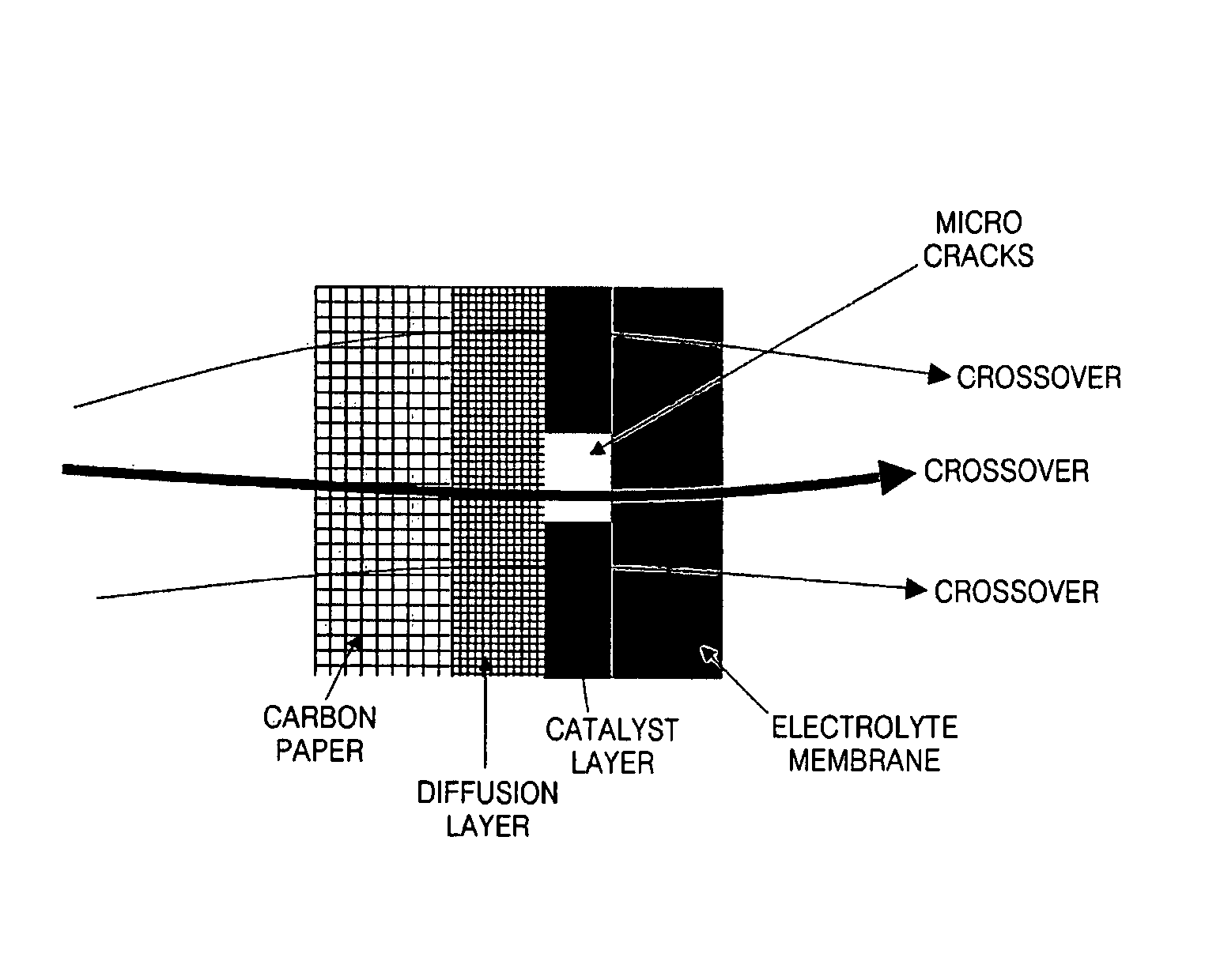
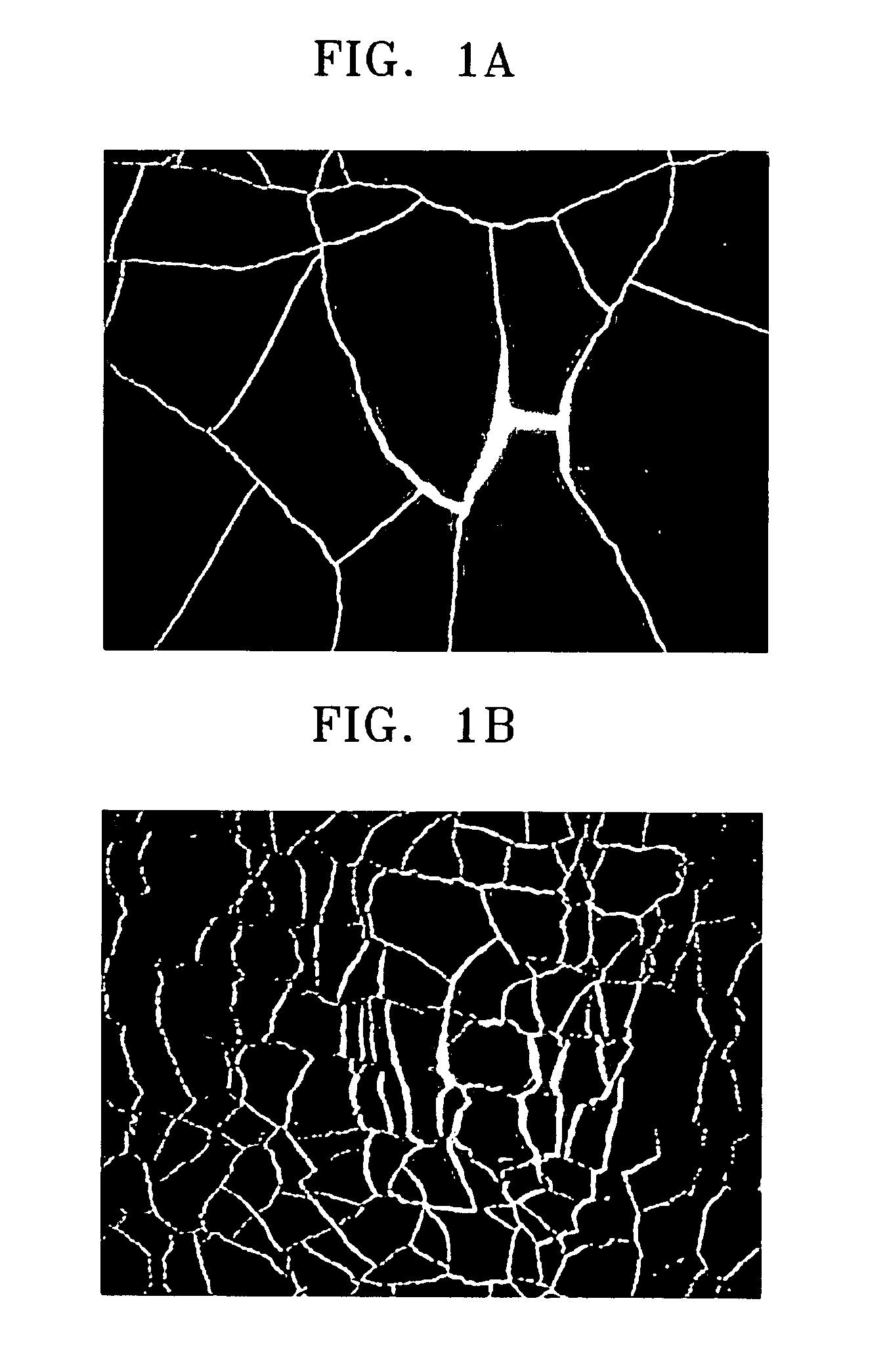
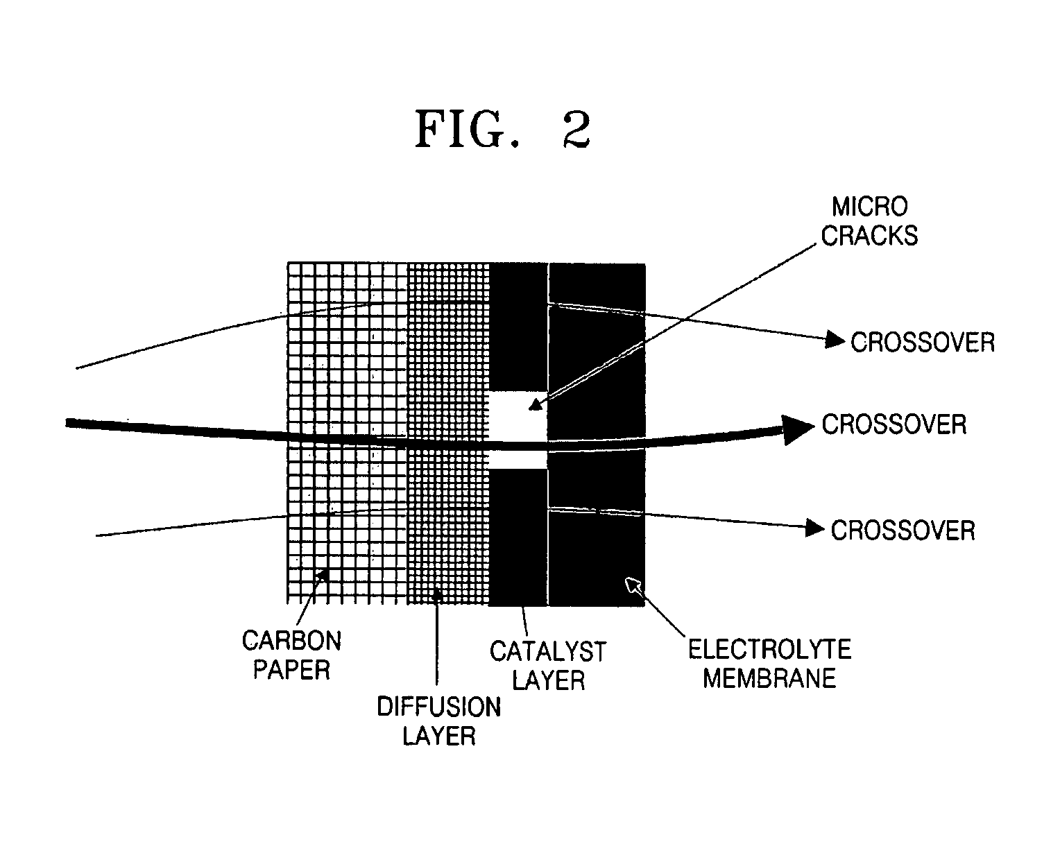
a catalyst coating and electrolyte technology, applied in the direction of cell components, final product manufacturing, sustainable manufacturing/processing, etc., can solve the problems of degrading the performance and long-term stability of the electrolyte membrane-electrode assembly, many micro cracks in the transferred catalyst layer, etc., to achieve the effect of reducing the resistance between the electrode catalyst layer and the electrolyte membran

Inactive Publication Date: 2013-01-01
SAMSUNG SDI CO LTD
View PDF12 Cites 0 Cited by
  • Summary
  • Abstract
  • Description
  • Claims
  • Application Information

AI Technical Summary

Benefits of technology

[0010]Aspects of the present invention provide a catalyst coated electrolyte membrane with improved performance and durability in which micro cracks of an electrode catalyst layer are minimized and thus the resistance between the electrode catalyst layer and an electrolyte membrane can be minimized, and crossover of a fuel, such as methanol, ethanol, other alcohols, methane, etc., to a cathode electrode is minimized, a fuel cell including the same, and a method of preparing the catalyst coated electrolyte membrane.

Problems solved by technology

The hot pressing process results in many micro cracks in the transferred catalyst layers because the electrolyte membrane and the catalyst layers are in different states before and after the transferring process.
Such micro cracks lead to high resistance between the catalyst layers and the electrolyte membrane and high crossover of methanol to the cathode electrode, thereby degrading the performance and long-term stability of the electrolyte membrane-electrode assembly.

Method used


Image

  • Catalyst coated electrolyte membrane, fuel cell including the same, method of preparing the catalyst coated electrolyte membrane
  • Catalyst coated electrolyte membrane, fuel cell including the same, method of preparing the catalyst coated electrolyte membrane
  • Catalyst coated electrolyte membrane, fuel cell including the same, method of preparing the catalyst coated electrolyte membrane

Examples


example 1

[0049]A Pt—Ru alloy as an anode metal catalyst was dispersed in a mixture of ultrapure distilled water, ethylene glycol, and 20 wt % NAFION ionomer solution (produced by Dupont Co.) to prepare a slurry. The prepared slurry was coated on a 50 μm-thick KAPTON film and then dried to prepare an anode catalyst layer transfer membrane. An anode catalyst layer was formed such that the concentration of the catalyst was 6 mg / cm2 based on the amount of the Pt—Ru alloy.

[0050]Pt as a cathode metal catalyst was dispersed in a mixture of ultrapure distilled water, ethylene glycol, and 20 wt % NAFION ionomer solution (produced by DUPONT CO.) to prepare a slurry. The prepared slurry was coated on a 50 μm-thick KAPTON film and then dried to prepare a cathode catalyst layer transfer membrane. A cathode catalyst layer was formed such that the concentration of the catalyst was 2 mg / cm2 based on the amount of Pt.

[0051]A NAFION (produced by DUPONT CO.) membrane having a thickness of 120 μm was used as an...

example 2

[0054]A catalyst coated electrolyte membrane was prepared in the same manner as in Example 1, except that the anode catalyst layer transfer membrane, the cathode catalyst layer transfer membrane, and the electrolyte membrane were preheated for 6 minutes. The surface image of the prepared catalyst coated electrolyte membrane is shown in FIG. 3B.


PUM

PropertyMeasurementUnit
lengthaaaaaaaaaa
widthaaaaaaaaaa
melting pointaaaaaaaaaa

Abstract

A catalyst coated electrolyte membrane including an anode catalyst layer and a cathode catalyst layer at opposite sides thereof, respectively, wherein micro cracks of the anode catalyst layer or cathode catalyst layer occupy 0.01-1 area % of the total area of the respective anode catalyst layer or cathode catalyst layer, a fuel cell including the same, and a method of preparing the catalyst coated electrolyte membrane. In the catalyst coated electrolyte membrane, micro cracks of the cathode catalyst layer or the anode catalyst layer can be minimized and thus the resistance between the electrode catalyst layer and an electrolyte membrane can be minimized, and crossover of a fuel, such as methanol, ethanol, other alcohols, methane, etc., to a cathode electrode can be minimized, and thus the catalyst coated electrolyte membrane has improved performance and durability.

Description

CROSS-REFERENCE TO RELATED PATENT APPLICATIONS[0001]This application claims the benefit of Korean Application No. 2006-12030, filed Feb. 8, 2006, in the Korean Intellectual Property Office, the disclosure of which is incorporated herein by reference.BACKGROUND OF THE INVENTION[0002]1. Field of the Invention[0003]Aspects of the present invention relate to a catalyst coated electrolyte membrane, a fuel cell including the same, and a method of preparing the catalyst coated electrolyte membrane, and more particularly, to a catalyst coated electrolyte membrane with improved performance and durability in which micro cracks of an electrode catalyst layer are minimized and thus the resistance between the electrode catalyst layer and an electrolyte membrane can be minimized, and crossover of a fuel to a cathode electrode is minimized, a fuel cell including the same, and a method of preparing the catalyst coated electrolyte membrane.[0004]2. Description of the Related Art[0005]Fuel cells are ...

Claims


Application Information

Patent Timeline
Patent Type & Authority Patents(United States)
IPC IPC(8): H01M8/06H01M8/24H01M8/10
CPCH01M4/8605H01M4/881H01M4/8814H01M4/8882H01M4/8892H01M4/8896H01M4/921H01M4/926H01M8/0239H01M8/1004H01M8/1009H01M8/1088Y02E60/523Y02P70/50Y02E60/50H01M4/88H01M4/86H01M8/02
Inventor KIM, JI-RAELEE, SEUNG-JAECHANG, HYUK
Owner SAMSUNG SDI CO LTD
Why Eureka
Try Eureka