Shock absorber

a technology of shock absorber and rod body, which is applied in the direction of shock absorber, spring/damper functional characteristics, cycle equipment, etc., can solve the problems of difficult to meet the strength conditions of rod body materials, and achieve the effect of improving performance and durability

Pending Publication Date: 2022-05-26
HITACHI ASTEMO LTD
View PDF0 Cites 0 Cited by
  • Summary
  • Abstract
  • Description
  • Claims
  • Application Information

AI Technical Summary

Benefits of technology

[0008]As a result of diligent studies, the present inventors have found that it is possible to improve performance of a stroke sensor by providing an intermediate member, which is made of a material with higher magnetic permeability than that of a rod pipe, between a rod pipe which is provided in a form of receiving an axial force of a shock absorber and can move in the axial direction and a coil provided inside this rod pipe. It was found that durability of the stroke sensor can be improved by providing the intermediate member in a form that allows movement in the axial direction. The invention has been completed based on such finding. The invention will be described below. In the following explanation, “provided in a configuration that receives an axial force” means that the shock absorber is provided in a form that prevents the shock absorber from moving in the axial direction by being fixed by other members provided around the shock absorber.
[0011]The invention can provide a shock absorber provided with a stroke sensor having improved performance and durability.

Problems solved by technology

However, among the materials having high magnetic permeability, there are materials which are difficult to satisfy strength conditions required for the rod.

Method used


Image

  • Shock absorber
  • Shock absorber
  • Shock absorber

Examples


first example

[0024]A shock absorber 20 of a first example will be described with reference to FIGS. 1 to 6.

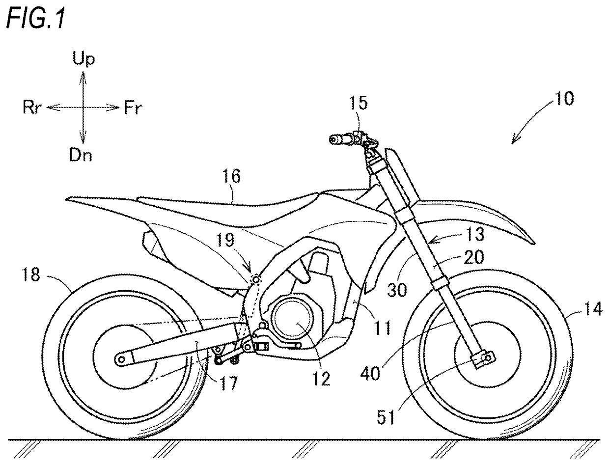
[0025]As illustrated in FIG. 1, the shock absorber 20 is used in a saddle-riding vehicle on which an occupant rides, such as a motorcycle and a tricycle, and as an example, is a hydraulic shock absorber applicable to a front fork of a motorcycle.

[0026]A motorcycle 10 includes a vehicle body 11, an engine 12 which is a power source supported in a lower center of the vehicle body 11, a front fork 13 provided at a front of the vehicle body 11, a front wheel 14 which is a wheel supported by the front fork 13, and a steering bar 15 connected to the front fork 13. The motorcycle 10 is provided with an occupant seat 16 in an upper center of the vehicle body 11 and includes a wheel support mechanism 17 which extends rearward from a rear portion of the vehicle body 11 and can swing in an up-down direction, a rear wheel 18 which is a wheel supported by the wheel support mechanism 17, and a rear suspe...

second example

[0070]FIG. 7 is an enlarged view illustrating a lower part of the shock absorber 200 and is illustrated in correspondence with FIG. 3 for explaining the shock absorber 20 of the first example. FIG. 8 is an enlarged view illustrating an intermediate portion in the axial direction of a shock absorber 200 and is shown in correspondence with FIG. 4 for explaining the shock absorber 20 of the first example.

[0071]The shock absorber 200 of the second example is characterized in that a first rod 270 corresponding to the first rod 70 illustrated in FIGS. 3 and 4 is provided with a first through hole 275 penetrating in a radial direction thereof and an intermediate member 276 corresponding to the intermediate member 170 illustrated in FIGS. 3 and 4 is provided with a second through hole 277 penetrating in the radial direction thereof. Other basic configurations are the same as those of the shock absorber 20 of the first example. In the description of the shock absorber 200, the same reference...

third example

[0079]FIG. 9 is an enlarged view illustrating an upper portion of the shock absorber 300 provided with a cable connection unit 390 and is illustrated in correspondence with FIG. 5 for explaining the shock absorber 20 of the first example. FIG. 10 is an enlarged view illustrating an appearance of the cable connection unit 390 and is illustrated in correspondence with FIG. 6 for explaining the shock absorber 20 of the first example. FIG. 11 is an enlarged view illustrating a cross section of the cable connection unit 390 and is illustrated in correspondence with FIG. 6 for explaining the shock absorber 20 of the first example.

[0080]The shock absorber 300 of the third example is characterized in that the cable connection unit 190 in the shock absorber 10 of the first example illustrated in FIGS. 5 and 6 is changed to the cable connection unit 390 illustrated in FIGS. 9 to 11 and other basic configurations are the same as those of the shock absorber 20 of the first example. In the descr...


PUM


Abstract

A shock absorber includes a hollow cylinder body extending in an up-down direction, a rod pipe located on an axis of the cylinder body, provided to be relatively movable in an axial direction of the cylinder body with respect to the cylinder body, and provided in a form of receiving a force in the axial direction, a rod-shaped support body extending inside the rod pipe with an upper end fixed, a stroke sensor including a coil and a conductor provided to be able to detect relative displacement of the rod pipe with respect to the support body, and a hollow intermediate member provided between the inner peripheral surface of the rod pipe and the support body to allow movement in the axial direction.

Description

CROSS-REFERENCE TO RELATED APPLICATIONS[0001]This application is based upon and claims the benefit of priority to Japanese Patent Application No. 2020-194937, filed on Nov. 25, 2020, the entire content of which is incorporated herein by reference in its entirety.FIELD OF THE INVENTION[0002]The present invention relates to a shock absorber suitable for use in a saddle-riding vehicle.BACKGROUND OF THE INVENTION[0003]A shock absorber is used for a front fork of a saddle-riding vehicle such as a motorcycle and a tricycle. In the front fork, for example, in order to figure out a running state of the saddle-riding vehicle, it may be required to detect a stroke amount of the shock absorber, which is an expansion and contraction amount of the front fork. Such a shock absorber is known, for example, in Japanese Patent No. 6625791.[0004]The shock absorber known in Japanese Patent No. 6625791 includes an outer tube with an upper end as a closed end and a lower end as an open end, an inner tube...

Claims


Application Information

Patent Timeline
Patent Type & Authority Applications(United States)
IPC IPC(8): F16F9/16F16F9/50F16F9/32
CPCF16F9/165F16F9/50F16F9/3292F16F2222/12F16F2234/02F16F13/007F16F2230/08F16F2230/18F16F2222/06F16F2230/42F16F2232/08B62K25/08B62K25/283B62J45/41B62J45/42B62K2025/044F16F2224/02F16F2228/066F16F2230/0047F16F2230/0052
Inventor IKEDA, DAISUKEKADOTA, NAO
Owner HITACHI ASTEMO LTD
Why Eureka
Try Eureka