Transmitter power monitor
- Summary
- Abstract
- Description
- Claims
- Application Information
AI Technical Summary
Benefits of technology
Problems solved by technology
Method used
Image


Examples
Embodiment Construction
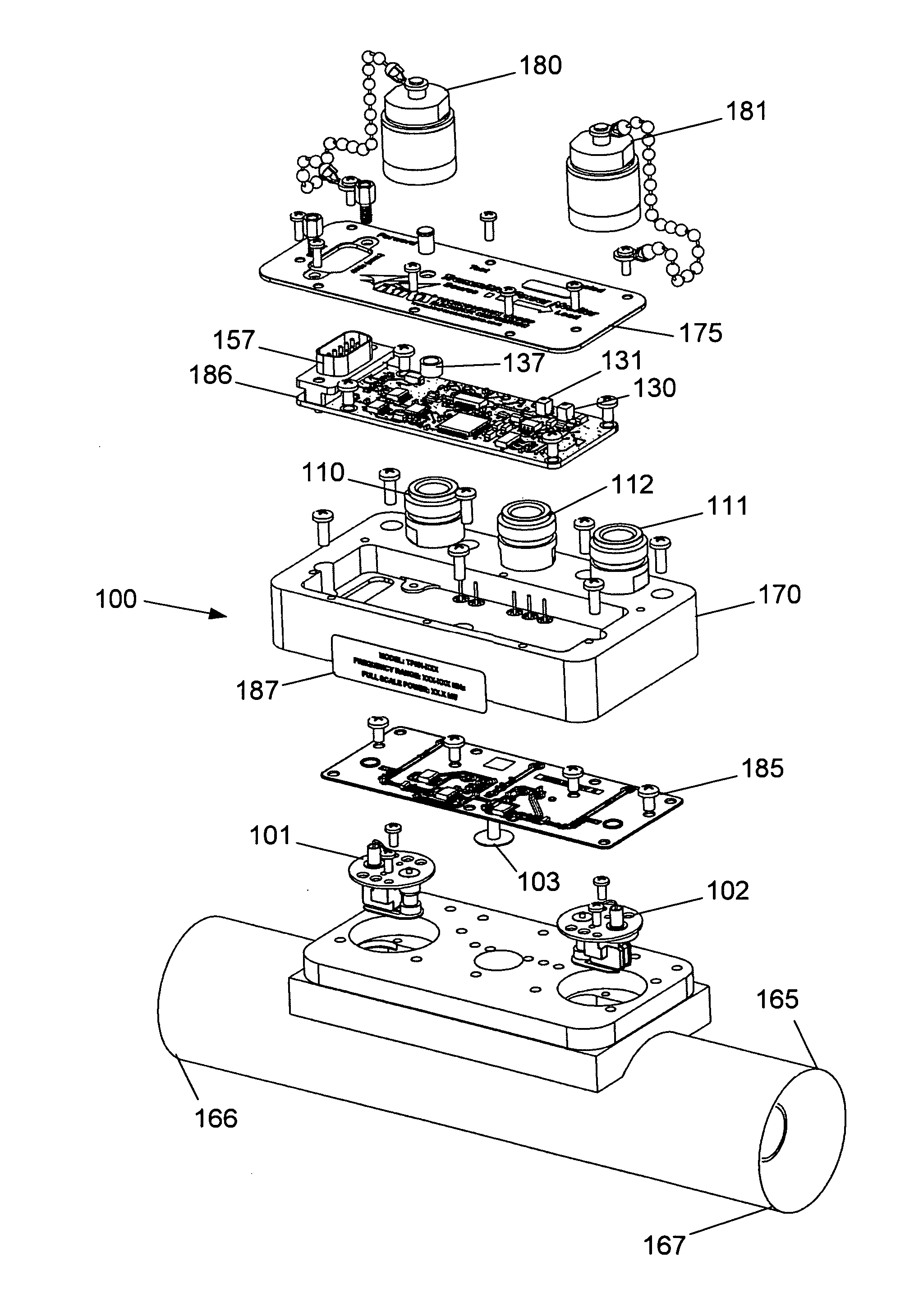
[0022]Referring more particularly to the drawings, there is shown an embodiment of the invention, a transmitter power monitor capable of being calibrated while operating under live conditions.
[0023]Referring to FIG. 1, a transmitter power monitor 100 comprises a transmission line section 165 having a transmitter end 166 and a load end 167. A rectangular body 170 is fastened to the top of the transmission line section 165. The body 170 has a cover 175. Forward and reflected directional couplers 101 and 102 and non-directional coupler 103 are located inside the body 170. In the preferred embodiment, non-directional coupler 103 is mounted on a RF board 185, while the RF board 185 is placed on top of forward and reflected couplers 101 and 102. All of the couplers 101, 102, and 103 interface with the RF board.
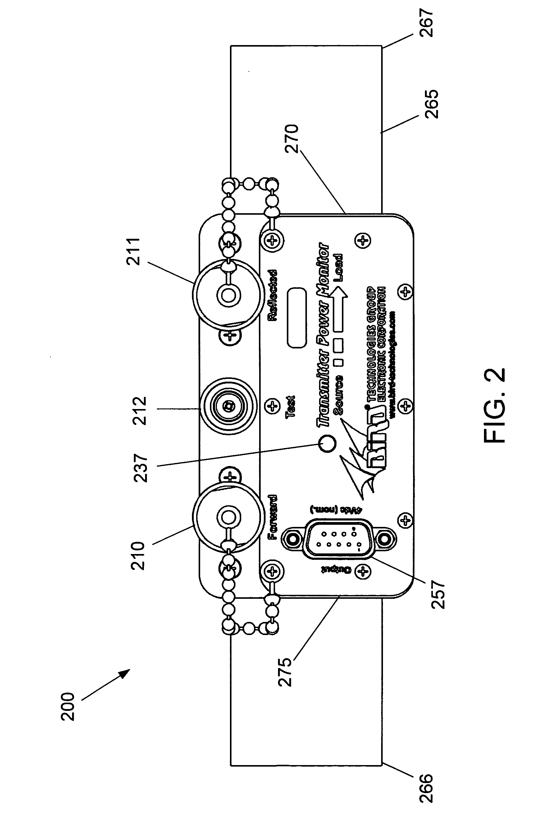
[0024]A logic board 186 is placed on top of and interfaces with the RF board 185. The logic board has a male DE9 9-pin D-sub socket 157, an LED 137, and forward and reflected calibr...
PUM
 Abstract
Description
Claims
Application Information