Radio frequency identification overlay network for fiber optic communication systems

Active Publication Date: 2010-04-22
TELESCENT
View PDF5 Cites 90 Cited by
  • Summary
  • Abstract
  • Description
  • Claims
  • Application Information

AI Technical Summary

Benefits of technology

[0012]In accordance with the system aspects of this invention, the RFID overlay system is comprised of one or more multiplexed RFID readers at one or more manual or automated fiber optic patchpanels and/or cross-connects, RF resonant fiber optic cables, and miniaturized

Problems solved by technology

The management of this portion of the network is a labor-intensive process involving manual record keeping, testing, debugging and cable patching.
According to BICSI News, up to 70% of network downtime is the result of cabling problems.
Network Systems DesignLine [Mar. 14, 2007] reported that “the number one cause of fiber optic network downtime is equipment damage resulting from human error, either through rough handling or improper cable routing”.
In contrast

Method used


Image

  • Radio frequency identification overlay network for fiber optic communication systems
  • Radio frequency identification overlay network for fiber optic communication systems
  • Radio frequency identification overlay network for fiber optic communication systems

Examples


Embodiment Construction

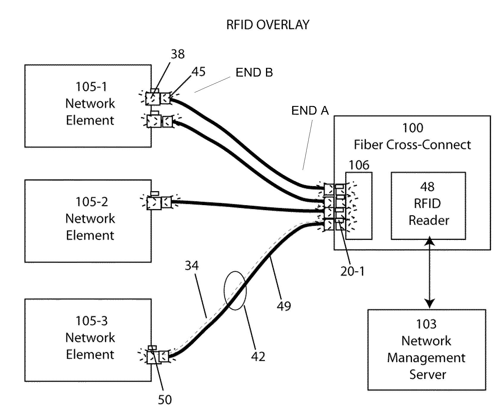
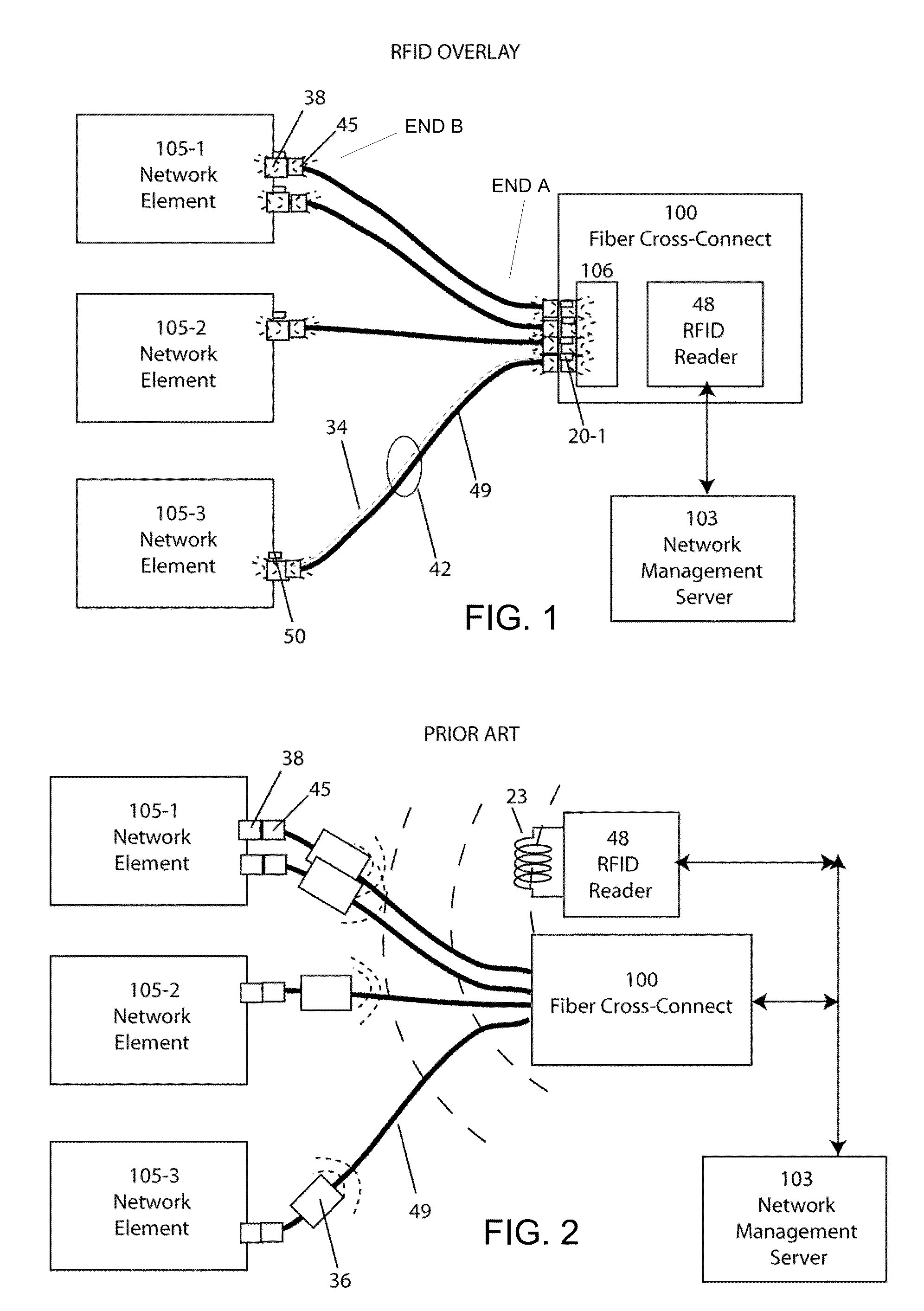
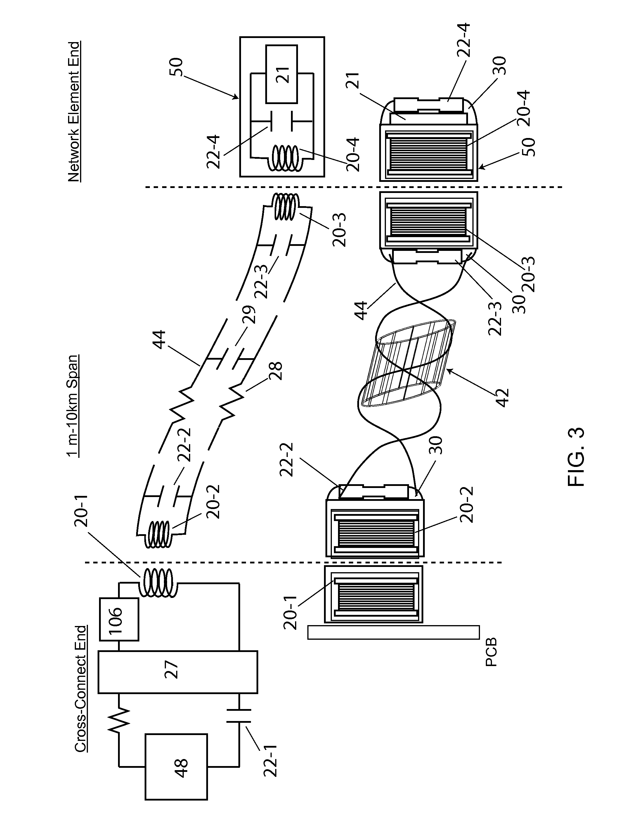
[0025]In this invention, a fully automated fiber optic physical layer mapping and inventory management system is disclosed (FIG. 1), comprised of an RFID overlay network wherein RFID tags 50, reduced in volume to less than 75 mm3 and responsive to 125 kHz RF excitation, are attached adjacent to fiber optic connector receptacles 38, such as those compatible with standard LC, SC, MT connectors 37, distributed to a multiplicity of network elements 105, such as electronic add / drop multiplexers or electronic cross-connects. The overlay aspect relates to the substantially parallel and identical paths followed by the electronic RF transmission lines 34 and the optical transmission lines 49. The overly system also utilizes resonant close coupling between inductor components 20, requiring that the adjacent reader antenna 20-1 to cable inductor 20-2, and cable inductor 20-3 to tag antenna 20-4 lie within 1 to 10 mm of one another. This ensures that only one tag is read out through any one cab...


PUM


Abstract

In this invention, a radio frequency identification overlay network that automates the discovery and configuration management of all physical fiber optic connections within a distributed communications network is disclosed. Miniaturized, low crosstalk RFID tags at a first fiber optic receptacle location and miniature, distributed, multiplexed reader antenna at a distant, second fiber optic receptacle location are joined by a fiber optic link which transmits both optical data and RF electronic signals. This electronic-fiber optic interface is comprised of two separated, miniaturized resonant antenna in communication with another through a resonant RF transmission line integral to the fiber optic cable. This RFID overlay network is comprised of multiplexed RFID readers, RF resonant fiber optic cables, and miniaturized RFID tags attached to the connector receptacles of network elements. The RFID overlay network interrogates tags automatically and remotely through the RF transmissive and optically transmissive fiber optic patch cords, eliminating the need for manual readout by technicians.

Description

REFERENCE TO RELATED APPLICATIONS[0001]This application is based on Provisional Patent Application No. 61 / 119503, filed on Dec. 3, 2008 and entitled “Autonomous Fiber Optic Networks”, and is a Continuation-in-Part of U.S. patent application Ser. No. 12 / 114,117, filed on May 12, 2008 and entitled “Electrically Traceable and Identifiable Fiber Optic Cables and Connectors”.FIELD OF THE INVENTION[0002]This invention relates to apparatus and systems to automate the management of optical fiber communication systems, and more particularly, to a distributed network of miniaturized radio frequency identification tags and electrically transmissive fiber optic cables that automatically determine the arrangement of physical interconnects across a network of fiber optic links.BACKGROUND OF THE INVENTION[0003]Layer-0, the fiber optic physical network layer, is the foundation of the global communications infrastructure for transmitting voice, data and video traffic. The management of this portion ...

Claims


Application Information

Patent Timeline
IPC IPC(8): H04B10/00
CPCG02B6/3895G06K7/10178G02B6/447G02B6/3817G02B6/562
Inventor KEWITSCH, ANTHONY STEPHEN
Owner TELESCENT
Why Eureka
Try Eureka