Method of building a database of mobile device beacon locations

a mobile device and location technology, applied in the field of building a database of mobile device beacon locations, can solve the problems of not all operators offering location application programming interfaces, not being able to determine the position of devices, and not being able to meet the needs of real-time tracking of a large user base,

Inactive Publication Date: 2011-05-19
PALRINGO
View PDF2 Cites 17 Cited by
  • Summary
  • Abstract
  • Description
  • Claims
  • Application Information

AI Technical Summary

Benefits of technology

In an implementation, the beacon sighting data includes an ID for each beacon and signal strength data associated with each beacon; and an iterative process calculates the optimal placement of beacons in a 2D or 3D topology using force directed graph calculations without the need for any of the mob

Problems solved by technology

However, if accurate positions of the visible beacons are not known, it may not be possible to determine the position of the devices.
Unfortunately, not all operators offer Location application programming interfaces (APIs).
Furthermore, the pricing scheme for such services usually involves per-l

Method used


Image

  • Method of building a database of mobile device beacon locations
  • Method of building a database of mobile device beacon locations
  • Method of building a database of mobile device beacon locations

Examples


example 1

Scenario

A user is driving down the A1 national route in England. She passes a known cell, followed by two unknown cells, before sighting another known cell.

Result:

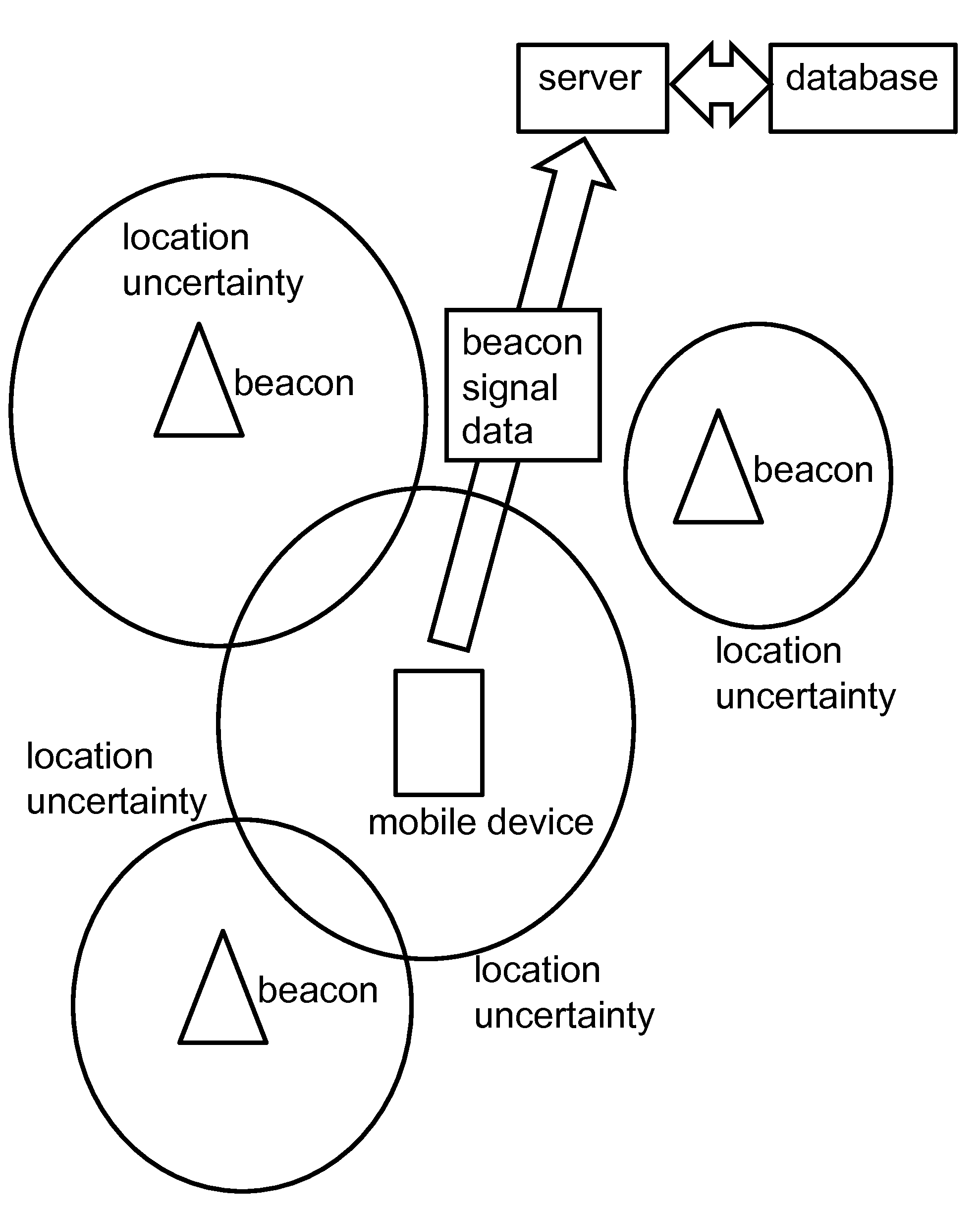
The algorithm assumes that the unknown beacons are spaced equidistantly on the geodesic line between the known beacons. This is shown in FIG. 4.

example 2

Scenario: The unknown beacons from the previous example are once again sighted, by a GPS-enabled device at the user position indicated in the right hand side of FIG. 5. Result: The algorithm refines the estimates for the unknown nodes based on the new information, giving an optimal layout for the mesh. This is shown in FIG. 5.

example 3

Visualisation of data collected from a single journey from Cramlington to Ponteland in England. Circular nodes were previously known. Square nodes show estimated positions for sighted nodes. This is shown in FIG. 6.

Expectations

The system will work internationally, across all operators. It can quickly and autonomously learn enough data to provide inaccurate estimates of the user's general area. As more data is fed into the system, the accuracy of the data will improve significantly. To speed up the process, the database can be seeded by:Operator LBS requests when stuck (no sighted cells are known)Taking data from the Google Maps Mobile Cell Identification (ID) database (we reverse engineered the protocol)GPS enabled devices, such as a handful of GPS enabled devices


PUM


Abstract

A method of building a database of beacon locations is disclosed. Mobile devices submit beacon sighting data to a server; the server using the beacon sighting data to build the database of beacon locations using force directed graph calculations. An iterative process calculates the optimal placement of beacons in a 2D or 3D topology of nodes and edges using force directed graph calculations.

Description

BACKGROUND OF THE INVENTION1. Field of the InventionThis invention relates to a method of building (e.g. creating, populating, updating or improving) a database of beacon locations. Beacons are the stations used to receive and transmit signals to mobile devices, such as mobile telephones, cell phones, smart phones, laptop computers and any other kinds of mobile wireless information device with voice and / or data capabilities. Beacons may transmit and receive data using GSM, WCDMA, UMTS, LTE, Wi-Fi, Bluetooth or any other wireless system or protocol. Beacons may be GSM, WCDMA etc basestations of any size, including large, fixed cell towers, as well as much smaller basestations, such as picocells and femtocells.2. Technical BackgroundMobile devices can execute software to periodically report unique identifiers and signal strengths of visible beacons. However, if accurate positions of the visible beacons are not known, it may not be possible to determine the position of the devices. So ...

Claims


Application Information

Patent Timeline
IPC IPC(8): G06F17/30G06N5/02
CPCH04W24/02H04W16/18
Inventor ROSINSKI, MARTIN
Owner PALRINGO
Why Eureka
Try Eureka