

Plasma generating apparatus
a technology of generating apparatus and plasma, which is applied in the direction of coating, chemical vapor deposition coating, electric discharge tube, etc., can solve the problems of non-uniform plasma distribution, non-uniform plating or etching
- Summary
- Abstract
- Description
- Claims
- Application Information
AI Technical Summary
Benefits of technology
Problems solved by technology
Method used
Image

Examples
first embodiment
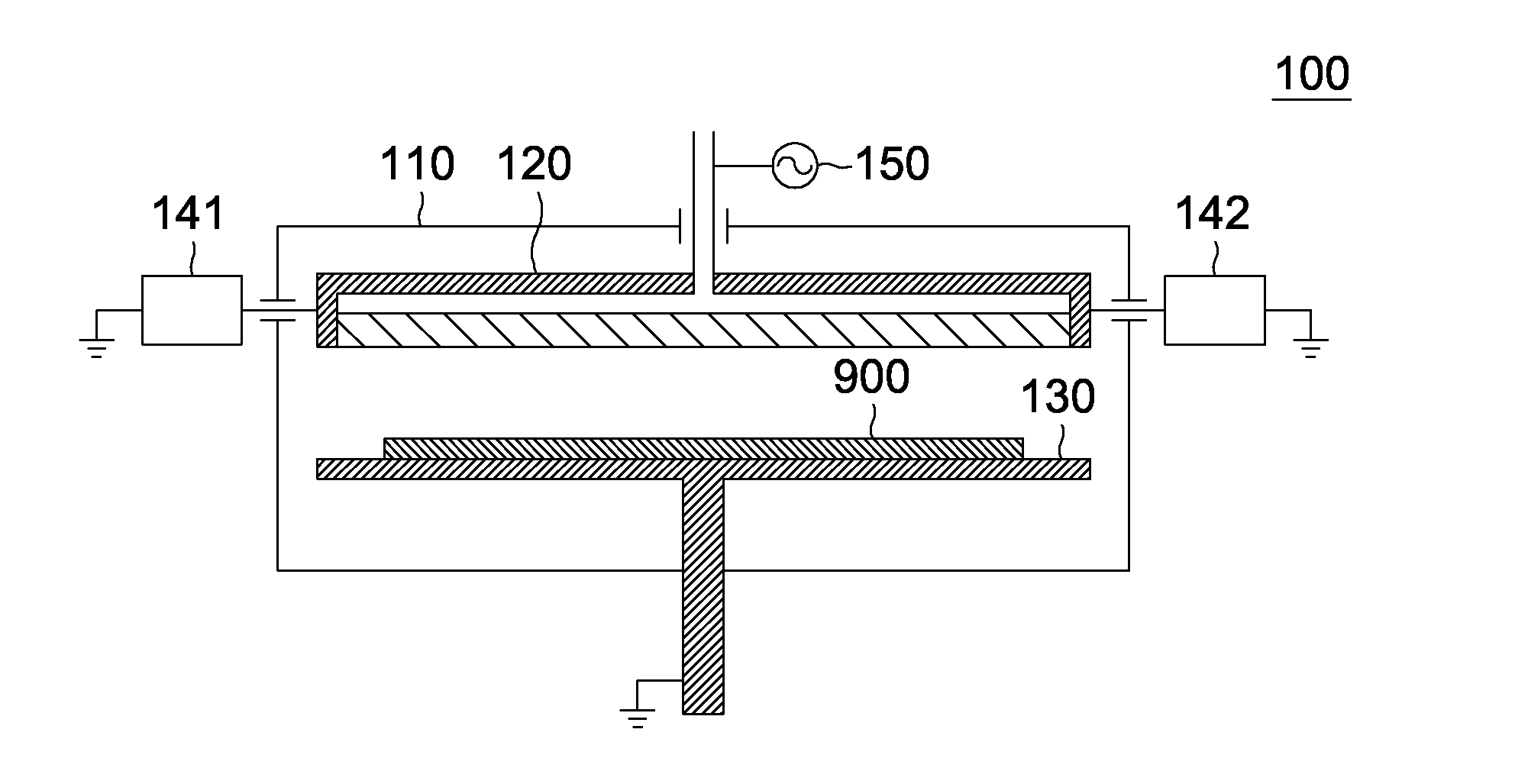
[0023]Referring to FIG. 1, plasma generating apparatus 100 includes a plasma process chamber 110, a top electrode board 120, a bottom electrode board 130, a first impedance modulator 141, a second impedance modulator 142, an RF power source 150, a vent hole and a vacuum pump (the vent hole and the vacuum pump are not illustrated in FIG. 1). The top electrode board 120 and the bottom electrode board 130 are disposed in parallel on top and bottom sides of the plasma process chamber 110. The top electrode board 120 is connected to the RF power source 150. Normally, the RF power source 150 is applied to the top electrode board 120, and the bottom electrode board 130 can be directly grounded or float. During manufacture, a gas is infused into the plasma process chamber 110 from the gas injection port (not illustrated in FIG. 1). When the RF power source 150 outputs sufficient RF power, a plasma is generated and maintained between the top electrode board 120 and the bottom electrode board...
second embodiment
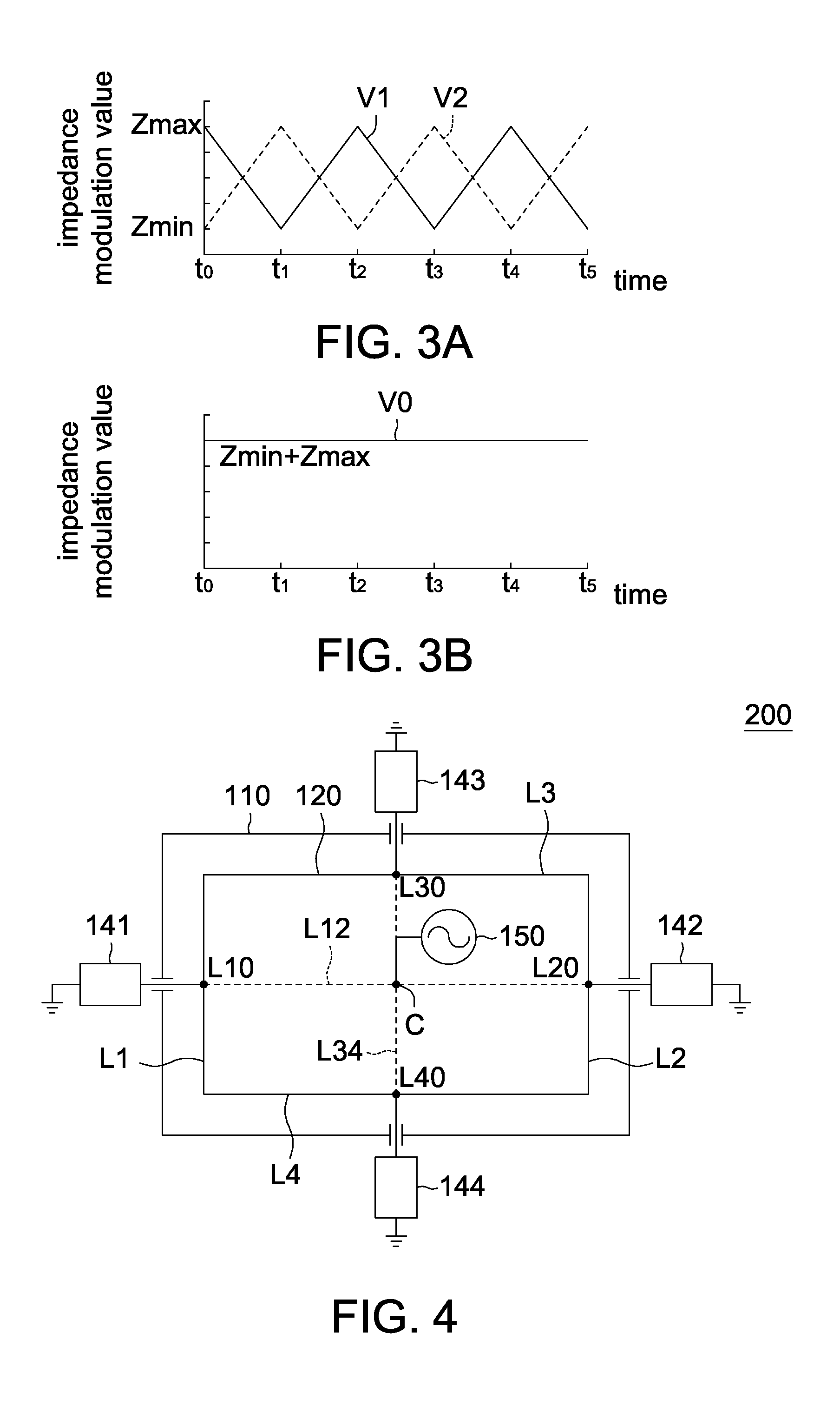
[0029]Referring to FIG. 4 and FIG. 5, plasma generating apparatuses 200 and 300 of the embodiment of the disclosure differs with the plasma generating apparatus 100 of the first embodiment in the quantity of the impedance modulators, and other similarities are not repeated here. As indicated in FIGS. 4 and 5, the plasma generating apparatus 200 of the present embodiment of the disclosure further includes a third impedance modulators 143 and a fourth impedance modulator 144 in pair in addition to the first impedance modulator 141 and the second impedance modulator 142 in pair.
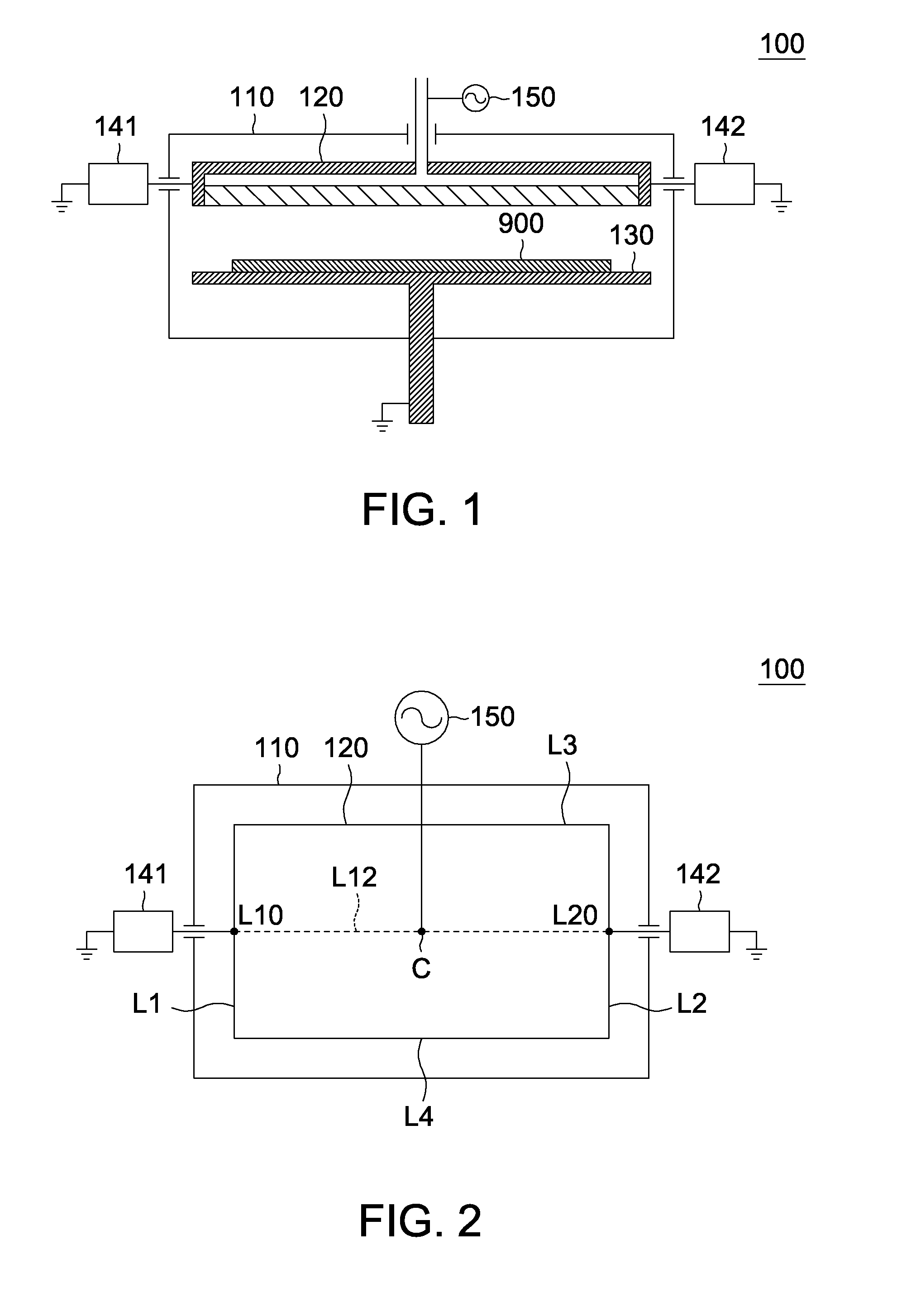
[0030]In the first embodiment, the connected line L12 of the first impedance modulator 141 and the second impedance modulator 142 passes through the center C of the top electrode board 120. Likewise, the connected line L34 of the third impedance modulators 143 and the fourth impedance modulator 144 also passes through the center C of the top electrode board 120. Thus, the first to fourth impedance modulators 141...
third embodiment
[0037]Referring to FIG. 7, plasma generating apparatus 400 of the present embodiment of the disclosure differs with the plasma generating apparatus 100 of the first embodiment in the quantity of the impedance modulators, and the similarities are not repeated here. As indicated in FIG. 7, the plasma generating apparatus 400 of the embodiment of the disclosure further includes a third impedance modulator 143 and a fourth impedance modulator 144 in pair, a fifth impedance modulator 145 and a six impedance modulator in pair 146 in pair, and a seventh impedance modulator 147 and a eighth impedance modulator 148 in pair in addition to the first impedance modulator 141 and the second impedance modulator 142 in pair. The first to eighth impedance modulators 141 to 148 are respectively parallel-connected to the middle point L10 of the first lateral side L1, the middle point L20 of the second lateral side L2, the first corner point A1, the second corner point A2, the middle point L30 of the t...
PUM
| Property | Measurement | Unit |
|---|---|---|
| Frequency | aaaaa | aaaaa |
| Electric impedance | aaaaa | aaaaa |
Abstract
Description
Claims
Application Information