Electromagnetic conductor reflecting plate and antenna array thereof and radar thereof and communication apparatus thereof

a technology of electromagnetic conductor and reflecting plate, which is applied in the direction of resonant antennas, instruments, and reradiation, etc., can solve the problems of large above reflector, increased manufacturing cost of antennas, and reduced antenna requirements

Active Publication Date: 2011-05-26
IND TECH RES INST
View PDF7 Cites 160 Cited by
  • Summary
  • Abstract
  • Description
  • Claims
  • Application Information

AI Technical Summary

Problems solved by technology

However, the trend of the communication apparatus of every kind is toward to the slim and small size, and therefore the required size of the antenna is becoming smaller.
Unfortunately, the size of the above reflector is large, and thus the manufacturing cost thereof is higher.
Although the manner can increase the energy of the reflected wave, it can not efficiently increase the antenna gain.

Method used


Image

  • Electromagnetic conductor reflecting plate and antenna array thereof and radar thereof and communication apparatus thereof
  • Electromagnetic conductor reflecting plate and antenna array thereof and radar thereof and communication apparatus thereof
  • Electromagnetic conductor reflecting plate and antenna array thereof and radar thereof and communication apparatus thereof

Examples


Embodiment Construction

[0030]Reference will now be made in detail to exemplary examples of the present disclosure, and exemplary examples of which are illustrated in the accompanying drawings. Wherever possible, the same reference numbers are used in the drawings and the description to refer to the same or like parts.

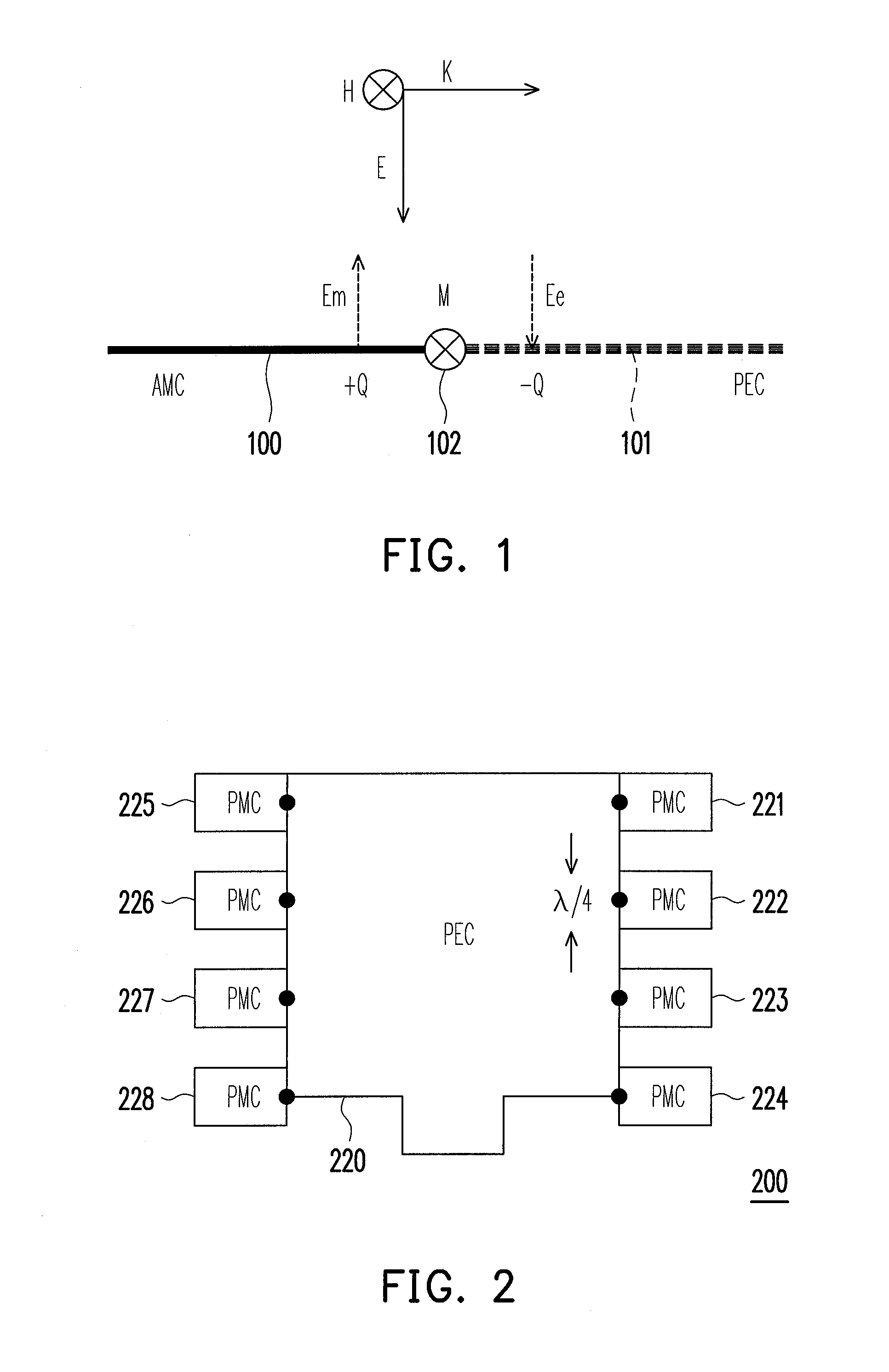
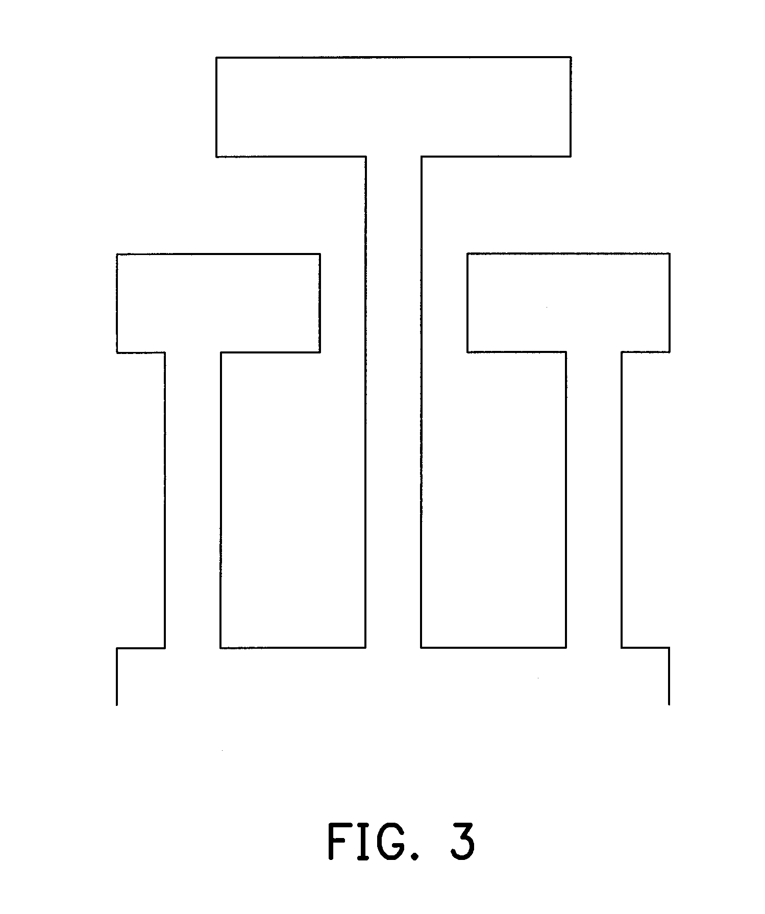
[0031]An exemplary example of the present disclosure provides a reflecting plate which is designed by combining boundary conditions of a PEC and an AMC. An antenna is placed on the reflecting plate to form an antenna array with high antenna gain, wherein the reflecting plate which is designed by combining boundary conditions of a PEC and an AMC is named an electromagnetic conductor reflecting plate.

[0032]When the radiated wave propagates to the electromagnetic conductor reflecting plate, the electromagnetic conductor reflecting plate equivalently generates a plurality of virtual radiation units. Thus, while the space positions of AMCs and PEC are appropriately designed, the number of the gene...


PUM


Abstract

An exemplary example of the present disclosure proposes an electromagnetic conductor reflecting plate including a perfect electronic conductor and at least two artificial magnetic conductors, wherein the each of the artificial magnetic conductor is disposed on arbitrary one side of the perfect electronic conductor, and a boundary between the perfect electronic conductor and each of the artificial magnetic conductor forms a virtual radiation unit. In addition, an exemplary example of the present disclosure further proposes an antenna array including an antenna and the electromagnetic conductor reflecting plate, wherein the antenna is disposed on the electromagnetic conductor reflecting plate.

Description

CROSS-REFERENCE TO RELATED APPLICATION[0001]This application claims the priority benefit of Taiwan application serial no. 98140003, filed on Nov. 24, 2009. The entirety of the above-mentioned patent application is hereby incorporated by reference herein and made a part of specification.BACKGROUND[0002]1. Technical Field[0003]The present disclosure generally relates to a structure of an antenna array, and more particularly to an electromagnetic conductor reflecting plate, an antenna array using the electromagnetic conductor reflecting plate, and a radar and a communication apparatus using the antenna array.[0004]2. Related Art[0005]Along with the development of the communication technology, the antenna is seen in the usual life. To focus the energy of the antenna, the antenna array having the reflector is generally designed in the communication apparatus, such that the gain of the antenna is improved. However, the trend of the communication apparatus of every kind is toward to the sl...

Claims


Application Information

Patent Timeline
Patent Type & Authority Applications(United States)
IPC IPC(8): G01S13/00H01Q1/00H01Q15/14
CPCG01S7/03H01Q1/38H01Q19/00H01Q9/0407H01Q1/48
Inventor TARNG, JENN-HWANCHANG, LI-YUANNIEN, CHIN-CHUNGYU, YA-CHUNGHUANG, JUN-YEN
Owner IND TECH RES INST
Why Eureka
Try Eureka