Method for dislaying measurement effective area in three-dimensional visual sensor and three-dimensional visual sensor

Active Publication Date: 2011-05-26
ORMON CORP
View PDF4 Cites 57 Cited by
  • Summary
  • Abstract
  • Description
  • Claims
  • Application Information

AI Technical Summary

Benefits of technology

[0024]According to the above aspect, the projection image suitable to the measurement target in the two-dimensional image is produced by performing the perspective transformation of the three-dimensional model, transformed into the state in which the position and attitude of the measurement target are expressed, into the coordinate system of the reference camera. Further, the z-coordinate based on the height set in the original three-dimensional model is set to each point of the projection image of the three-dimensional model to perform the perspective transformation processing, thereby producing the projection image in which the position and attitude of the measurement target are expressed in the three-dimensional manner. Therefore, the user can easily recognize whether the measur

Problems solved by technology

However, because a size of the image projected to an imaging surface of the camera is decreased as the imaging target is moved farther away from the viewpoint of the camera, it is difficult for the user to recognize how much the set effective area spreads or whether the spread range is proper.
Therefore, such display is su

Method used


Image

  • Method for dislaying measurement effective area in three-dimensional visual sensor and three-dimensional visual sensor
  • Method for dislaying measurement effective area in three-dimensional visual sensor and three-dimensional visual sensor
  • Method for dislaying measurement effective area in three-dimensional visual sensor and three-dimensional visual sensor

Examples


Embodiment Construction

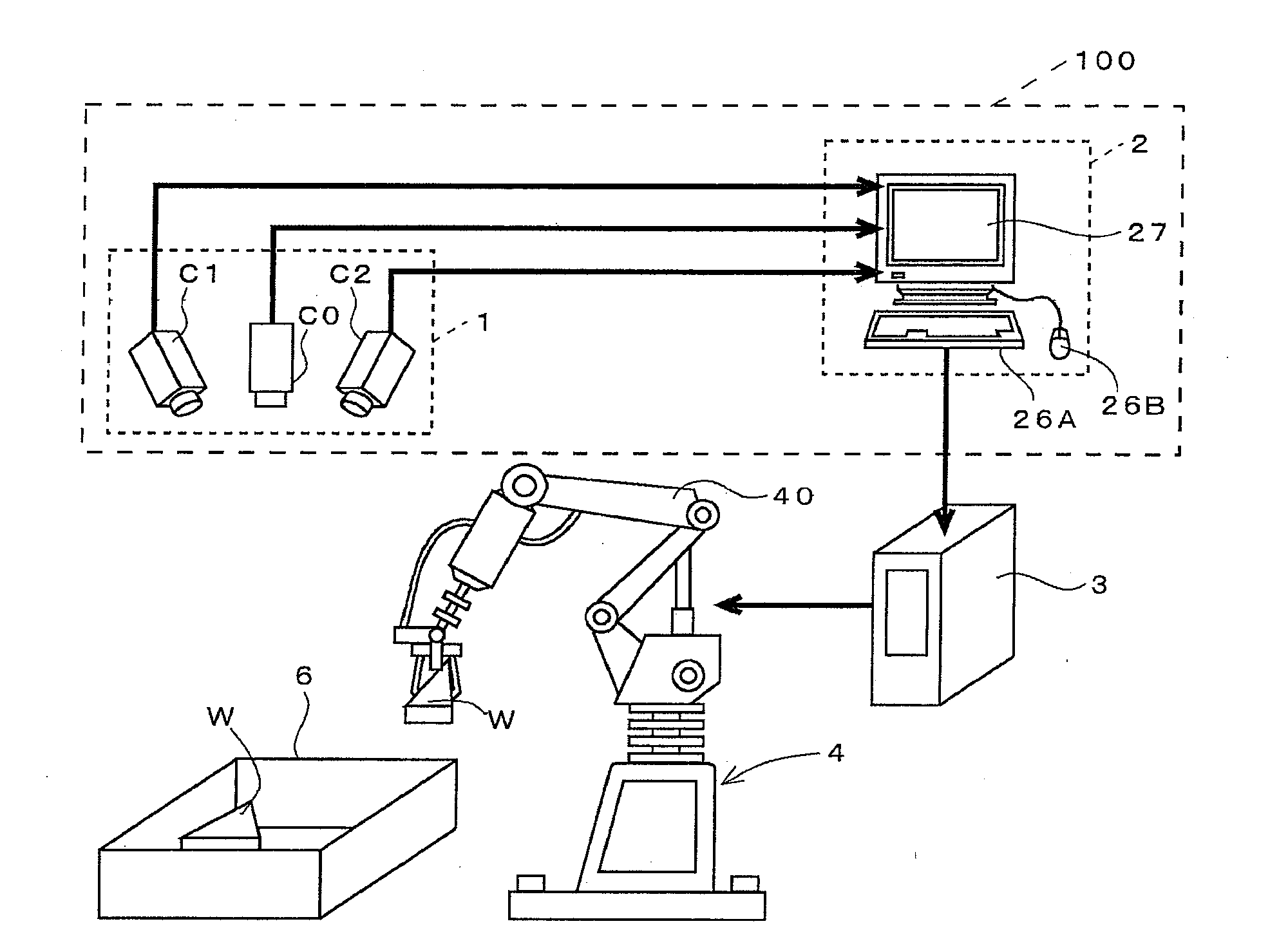
[0034]FIG. 1 shows an example of a picking system to which a three-dimensional visual sensor is introduced.

[0035]The picking system is used to pick up a workpiece W accommodated in a container box 6 in a factory one by one to convey the workpiece W to a predetermined position. The picking system includes a three-dimensional visual sensor 100 that recognizes the workpiece W, a multijoint robot 4 that performs actual work, and a robot control device 3 that controls an operation of the robot 4.

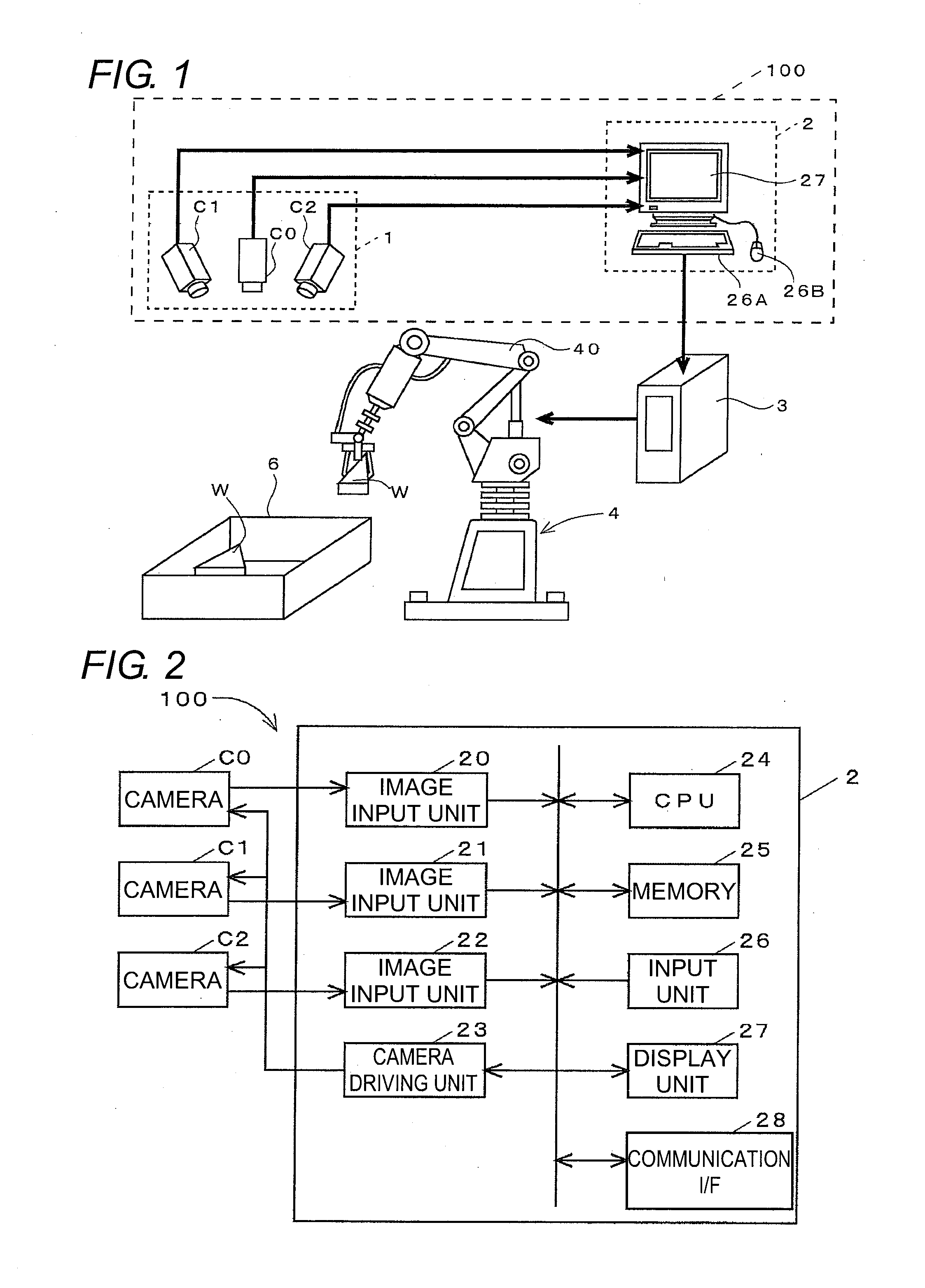
[0036]The three-dimensional visual sensor 100 includes a stereo camera 1 and a recognition processing device 2.

[0037]The stereo camera 1 includes three cameras C0, C1, and C2. The central camera C0 is disposed while an optical axis of the camera C0 is oriented toward a vertical direction (that is, the camera C0 takes a front view image), and the right and left cameras C1 and C2 are disposed while optical axes of the cameras C1 and C2 are inclined.

[0038]The recognition processing device 2 is a per...


PUM


Abstract

One of stereo cameras is set such that a front view of a support surface of a workpiece is imaged, an image produced by the camera is displayed, and a range of an area where measurement processing is enabled is assigned by a rectangular frame. A manipulation assigning an upper limit and a lower limit of a height measurement range is accepted. When each assignment is fixed, zero is set as a z-coordinate to each constituent pixel of an image to which the rectangular frame is set, and a z-coordinate based on the upper limit of the height measurement range and a z-coordinate based on the lower limit are set to coordinates corresponding to the rectangular frame. Perspective transformation of three-dimensional information produced by the setting is performed from a direction of a line of sight set by a user, a produced projection image is displayed on a monitor.

Description

BACKGROUND OF THE INVENTION[0001]1. Technical Field[0002]The present invention relates to a technology of displaying a setting state of an area where measurement processing is enabled in a three-dimensional sensor in which a measurement target (hereinafter, occasionally referred to as “workpiece”) and a support surface of the measurement target are imaged with a stereo camera to perform three-dimensional measurement of the measurement target using a produced stereo image.[0003]2. Related Art[0004]The three-dimensional visual sensor includes a function of restoring three-dimensional information on a target by stereo measurement and a function of matching the restored three-dimensional information with previously registered three-dimensional model to recognize a position and an attitude of the target. The three-dimensional visual sensor is used to recognize a component that is a grasping target of a picking robot or to inspect a component or a shape of a completed product.[0005]The ap...

Claims


Application Information

Patent Timeline
IPC IPC(8): H04N13/02H04N13/243
CPCG05B2219/37017G06T7/0075H04N13/0239H04N13/0242G06T2207/30164G06T7/0046G06T2200/24G06T2207/10012G06T2207/10028H04N2013/0081G06T7/75G06T7/593H04N13/239H04N13/243
Inventor FUJIEDA, SHIROTANENO, ATSUSHITAKAHASHI, REIJIYOSHINO, MASANAOUKAI, KENICHI
Owner ORMON CORP
Why Eureka
Try Eureka