Carbonate spring producing system

a technology of carbonate springs and producing systems, applied in the direction of liquid transfer devices, process and machine control, combustible gas purification/modification, etc., can solve the problems of large problem, running cost, and the inability to dissolve carbonic acid gas in hot water at 100% concentration, so as to increase and decrease the amount of bubbles

Inactive Publication Date: 2011-05-26
MITSUBISHI RAYON CO LTD
View PDF9 Cites 3 Cited by
  • Summary
  • Abstract
  • Description
  • Claims
  • Application Information

AI Technical Summary

Benefits of technology

[0026]The carbonate spring producing system of the invention has the main feature in which the bubble detection means is provided. The anomaly of the carbonate springs can be detected in the gas-liquid separator or the liquid lead-out pipe by including the bubble detection means. In the invention, the un-dissolved carbonic acid gas (bubble amount of carbonate spring) of the carbonate springs led out to the liquid lead-out pipe the from the gas-liquid separator can always be monitored, and the opening and closing of the carbonic acid gas supply line can be controlled based on the increase and decrease in bubble amount.
[0027]For example, an ultrasonic sensor, a photosensor, an ultraviolet ray sensor, a floating type level sensor, an electrostatic capacity type level sensor, and a pressure difference type level sensor can be used as the bubble detection means.
[0028]The generation of the un-dissolved carbonic acid gas can be detected in the carbonate springs led out to the liquid lead-out pipe by including the above configuration. Therefore, in the carbonate springs led out to the liquid lead-out pipe, the anomaly can be monitored by always sampling the bubble amount or by sampling the bubble amount at regular time intervals.
[0029]The invention can include the hot water circulating means for circulating the hot water in the bath as the hot water supply means. The bubble detection means can be included in a one-pass type carbonate spring producing system and a circulation type carbonate spring producing system. In the one-pass type carbonate spring producing system, the carbonate springs are produced by passing the hot water through the carbonic acid gas dissolver once. In the circulation type carbonate spring producing system, the hot water in the bath is circulated from a circulating pump through the carbonic acid gas dissolver.
[0030]In the bubble detection means including the ultrasonic transmitter, the ultrasonic receiver, and the determination unit, when the carbonic acid gas bubble is contained in the carbonate springs flowing in the liquid lead-out pipe, the ultrasonic wave transmitted from the ultrasonic transmitter is diffused by the bubble, and the attenuated ultrasonic wave is received by the ultrasonic receiver. When the intensity of the ultrasonic wave received by the ultrasonic receiver is lowered below the predetermined threshold, the carbonic acid gas bubbles not lower than a predetermined amount exist in the carbonate springs flowing in the liquid lead-out pipe.
[0031]When the determination unit determines that the carbonic acid gas bubbles not lower than the predetermined amount exist in the carbonate springs flowing in the liquid lead-out pipe, namely, when the determination unit detects that the ultrasonic intensity is lowered below the predetermined threshold, the determination unit outputs the abnormal signal.

Problems solved by technology

However, even if such carbonic acid gas dissolvers are used, the carbonic acid gas cannot be dissolved in the hot water at the concentration of 100%.
In this case, un-dissolved carbonic acid gas is wastefully emitted in the atmosphere, which generates a large problem from the viewpoint of running cost.
The un-dissolved carbonic acid gas mixed in a bubble in the carbonate springs is emitted into a bath room, and the bath room is in the high concentration atmosphere of the carbonic acid gas in the case where a large amount of carbonate springs is produced like full immersion bath, which possibly has an adverse affect on a human body.

Method used


Image

  • Carbonate spring producing system
  • Carbonate spring producing system
  • Carbonate spring producing system

Examples


example 1

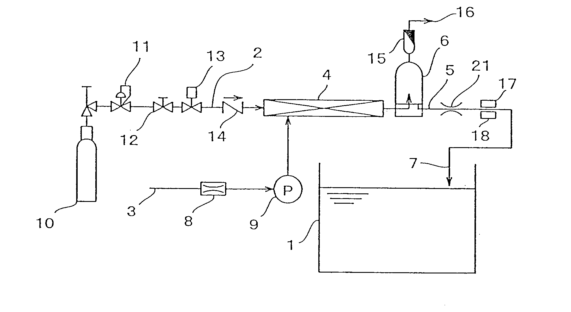
[0141]The one-pass type carbonate spring producing system shown in FIG. 1 is used in Example 1. The control is performed such that the electromagnetic valve 13 of the carbonic acid gas supply line 2 opened during the operation of the carbonate spring producing system is cut off when the reception signal received from the ultrasonic receiver 18 becomes not more than the predetermined threshold. In this state of things, the carbonate springs are produced.

[0142]The water heater supplies the hot water having the temperature of 40° C. to the carbonic acid gas dissolver 4 at 16 L (liter) per minute, and the carbonic acid gas bomb 10 supplies the carbonic acid gas to the carbonic acid gas dissolver 4 at 12 L (liter) per minute. The maximum value (when the carbonic acid gas is not led out) of the reception signal by the ultrasonic receiver 18 is 7.0 mV, and the predetermined threshold is set at 4.0 my. For a free carbonate concentration in the produced carbonate springs, when the carbonate ...

example 2

[0143]The carbonate springs are produced on the same conditions as Example 1 except that the un-dissolved carbonic acid gas emission line 16 is closed to disable the ability of the gas-liquid separator 6 to separate the gas and liquid. The reception signal of the ultrasonic receiver 18 immediately becomes 1.0 mV, which is lower than the predetermined threshold, to close the electromagnetic valve 13 of the carbonic acid gas supply line 2. The carbonic acid gas concentration of the bath water surface is lower than 0.25% in the bath 1, and the carbonic acid gas concentration is not more than the threshold limit value.

example 3

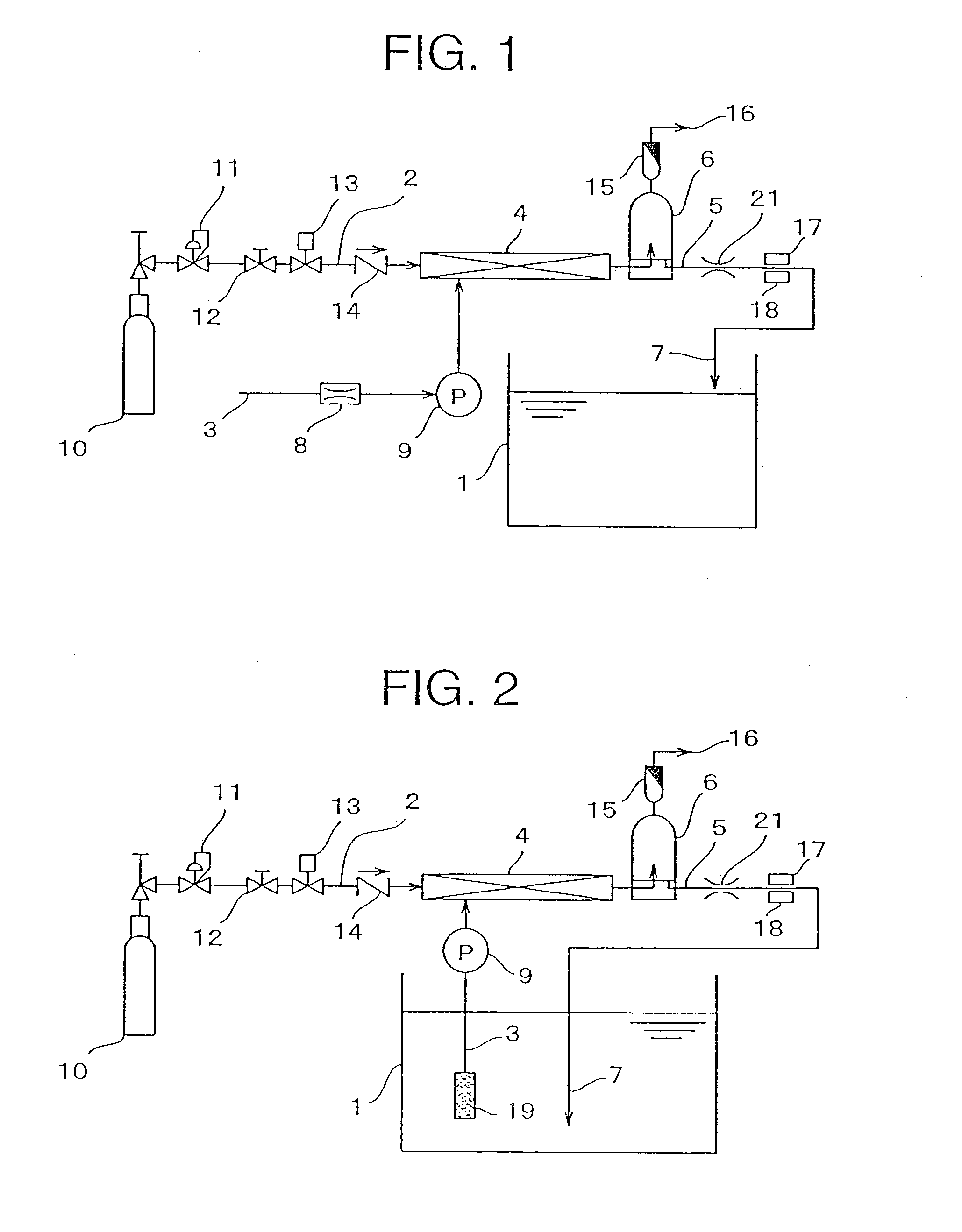
[0145]The bubble detection means in which the liquid level sensor 19 is arranged in the gas-liquid separator 6 is used in the circulation type carbonate spring producing system shown in FIG. 2. When the liquid level becomes lower than a predetermined level in the gas-liquid separator 6, the liquid level sensor 19 performs the control so as to cut off the electromagnetic valve 13 of the carbonic acid gas supply line 2 which is opened during the operation of the carbonate spring producing system. In this state of things, the carbonate springs are produced.

[0146]The hot water of the bath 1 has the temperature of 40° C., the amount of hot water is 200 L, the circulation flow rate of the pump 9 is set at 13 L (liter) per minute, and the carbonic acid gas bomb 10 supplies the carbonic acid gas to the carbonic acid gas dissolver 4 at 8 L per minute. The static mixer is used as the carbonic acid gas dissolver 4. A height of a space inside the gas-liquid separator 6 is 200 mm, and the liquid...


PUM

PropertyMeasurementUnit
temperatureaaaaaaaaaa
concentrationaaaaaaaaaa

Abstract

A carbonate spring producing system includes a gas-liquid separator (6) which is connected on the downstream side of a carbonic acid gas dissolver (4). A carbonic acid gas supply means (10) and hot water supply means are connected to the carbonic acid gas dissolver (4). A liquid lead-out pipe (5) is connected to the gas-liquid separator. Preferably an un-dissolved carbonic acid gas lead-out pipe (23) is connected on the upstream sides of the gas-liquid separator (6) and the carbonic acid gas dissolver (4). The un-dissolved carbonic acid gas lead-out pipe (23) includes a control valve (25), a compressor (27), and a liquid level detection means (22). The control valve (25) controls a flow rate of un-dissolved carbonic acid gas from the gas-liquid separator. The liquid level detection means (22) measures a liquid level of the gas-liquid separator. Control means (28) controls the flow rate of the supplied carbonic acid gas and the flow rate of the supplied un-dissolved carbonic acid gas based on the gas-liquid separator liquid level detected by the detection means (22). An amount of un-dissolved carbonic acid gas in the gas-liquid separator is always monitored, so that the un-dissolved carbonic acid gas in the hot water can securely be separated and removed by the gas-liquid separator, and the separated and removed un-dissolved carbonic acid gas can be redissolved.

Description

CROSS REFERENCE TO RELATED APPLICATIONS[0001]This application is a Divisional patent application of U.S. application Ser. No. 10 / 586,162, filed Jul. 14, 2006, which is the U.S. National Stage patent application of PCT International Application No. PCT / JP2005 / 000194 filed Jan. 11, 2005, which designated the U.S. and was not published under PCT Article 21 (2) in English, and this application claims the priority from Japanese Application No. 2004-007008 filed Jan. 14, 2004, and Japanese Application No. 2004-191016, filed Jun. 29, 2004, the complete disclosures of each of the aforesaid applications are incorporated herein by reference.TECHNICAL FIELD[0002]The present invention relates to a carbonate spring producing system which enables un-dissolved carbonic acid gas to be redissolved while monitoring abnormal generation of the un-dissolved carbonic acid gas.BACKGROUND ART[0003]Because the carbonate springs have an excellent heat retaining effect, the carbonate springs is used in a bath...

Claims


Application Information

Patent Timeline
Patent Type & Authority Applications(United States)
IPC IPC(8): B01J19/00A61H33/02B67D7/80
CPCA61H33/02Y10S261/07A61H33/60B01F3/04099B01F23/23
Inventor SUZUKI, SATOSHIOOYACHI, KENSAKAKIBARA, HIROKISATOU, MASAAKIITAKURA, MASANORITASAKA, HIROSHI
Owner MITSUBISHI RAYON CO LTD
Why Eureka
Try Eureka