Connector

Inactive Publication Date: 2011-05-26
DNOVA CORP
View PDF4 Cites 13 Cited by
  • Summary
  • Abstract
  • Description
  • Claims
  • Application Information

AI Technical Summary

Benefits of technology

[0010]A primary objective of the present invention lies in providing the connector, wherein a connector is defined with an opening for connecting a USB (Universal Serial Bus) connector. The connector being primarily assembled from a hollow casing, a first base and a second base, in which one end of the hollow casing is defined with the aforementioned opening, and two side walls at the rear of the hollow casing are respectively formed with a position fixing portion extending away from the opening. Moreover, the first base and the second base are fixedly combined together, and after combination, two sides thereof are respectively formed w

Problems solved by technology

However, when USB 2.0 transmission rates were unable to meet user needs, then USB 3.0 was developed.
However, the outer casing of connectors of general devices are not provided with a position retaining function, often causing displacement of the connector and errors occurring when in use.
However, assembly methods and specifications of USB

Method used


Image

  • Connector
  • Connector
  • Connector

Examples


Example

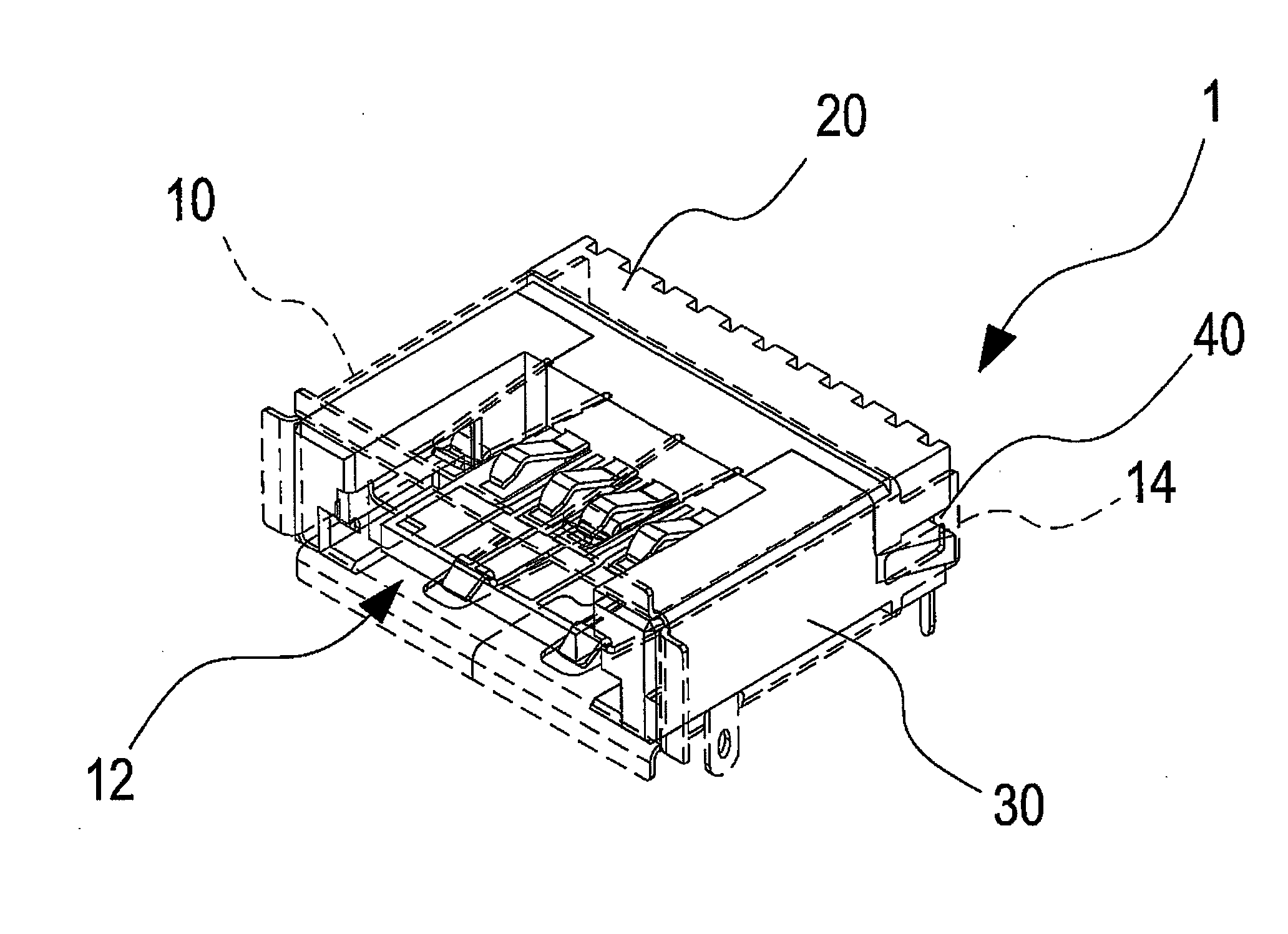
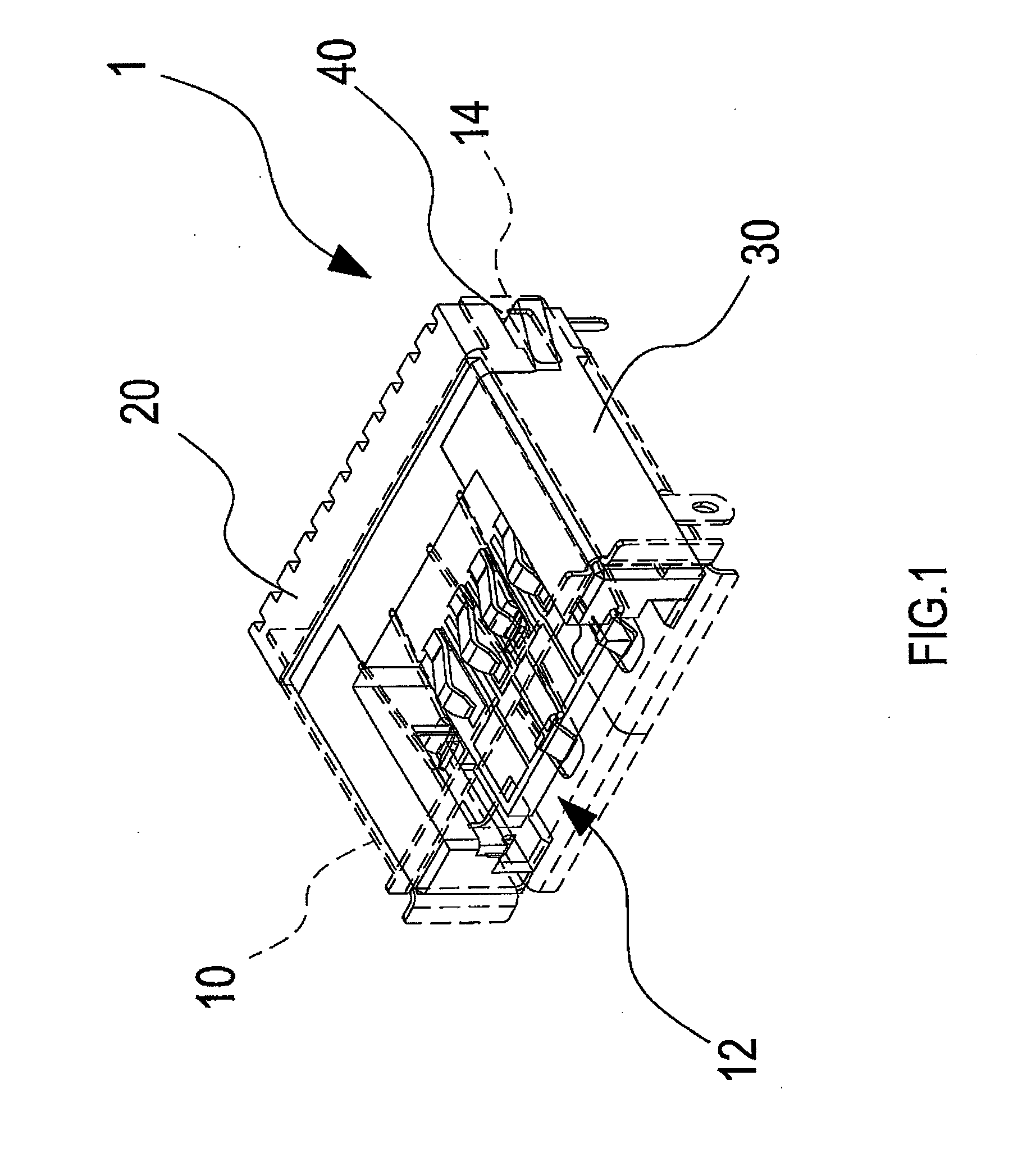
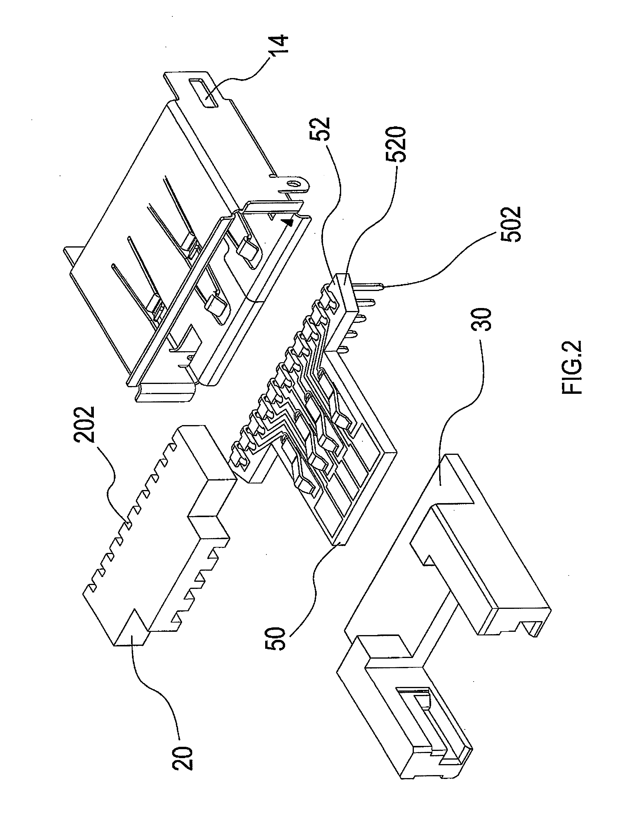
[0022]Referring to FIG. 1 and FIG. 2, which show an elevational schematic view and an exploded schematic view respectively of a preferred embodiment of the present invention, and it can be clearly seen from the drawings that a connector 1 of the present invention is defined with an opening 12 for connecting a USB (Universal Serial Bus) connector. The connector 1 is primarily assembled from a hollow casing 10, a first base 20 and a second base 30, in which one end of the hollow casing 10 is defined with the aforementioned opening 12, and two side walls at the rear of the hollow casing 10 are respectively formed with a position fixing portion 14 extending away from the opening 12. Moreover, the first base 20 is formed with a plurality of grooves 202, and the grooves 202 are used to enable corresponding disposition of a plurality of pins 502 on a printed circuit tongue 50 therein. In addition, the first base 20 and the second base 30 are fixedly combined together, and after combination...


PUM


Abstract

The present invention relates to a connector, wherein a connector is defined with an opening for connecting a USB connector. The connector is mainly assembled from a hollow casing, a first base and a second base, and two rear side walls of the hollow casing are respectively formed with a position fixing portion extending away from the opening. Moreover, after fixedly combining together the first base and the second base, two sides thereof are respectively formed with a guiding portion, which enable fixing portions extending from two sides of a printed circuit tongue to effect sliding inserted disposition. After assembly of the bases with the printed circuit tongue, then the fixing portions enable fastening to the position fixing portions. Accordingly, the bases not only enable achieving the objective of product customization, but also retaining positioning of the connector is enabled to prevent errors from occurring due to displacement.

Description

BACKGROUND OF THE INVENTION[0001](a) Field of the Invention[0002]The present invention provides a connector, and more particularly provides a connector that enables changing the assembled form according to user needs, while at the same time retaining positioning of the connector.[0003](b) Description of the Prior Art[0004]Current use of electronic equipment is considerably widespread, with connectors being primarily used to establish a connection relation between electronic equipments. Moreover, the use of connectors on current printed circuit tongues is already extremely common, such as the various forms of connector ports, which are all completed via connectors. Printed circuit tongues of all types of electronic products, including familiar devices such as computer motherboards, mobile phone printed circuit tongues, and the like, are all equipped with connectors enabling connection with external devices, thereby enabling mutual connection between electronic products and data excha...

Claims


Application Information

Patent Timeline
IPC IPC(8): H01R24/00
CPCH01R12/724H01R13/6582H01R13/502
Inventor CHUNG, HSUAN-HO
Owner DNOVA CORP
Why Eureka
Try Eureka