
Spinal Surgical Implant and Related Methods

Active Publication Date: 2011-05-26
NUVASIVE
View PDF100 Cites 99 Cited by
  • Summary
  • Abstract
  • Description
  • Claims
  • Application Information

AI Technical Summary

Benefits of technology

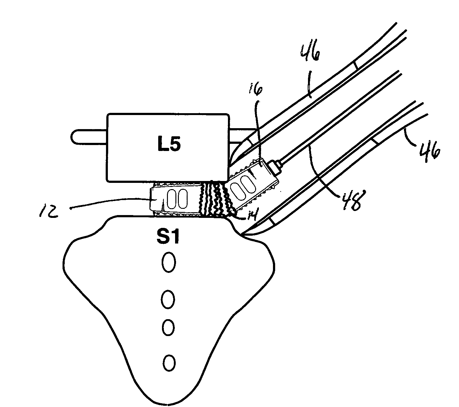
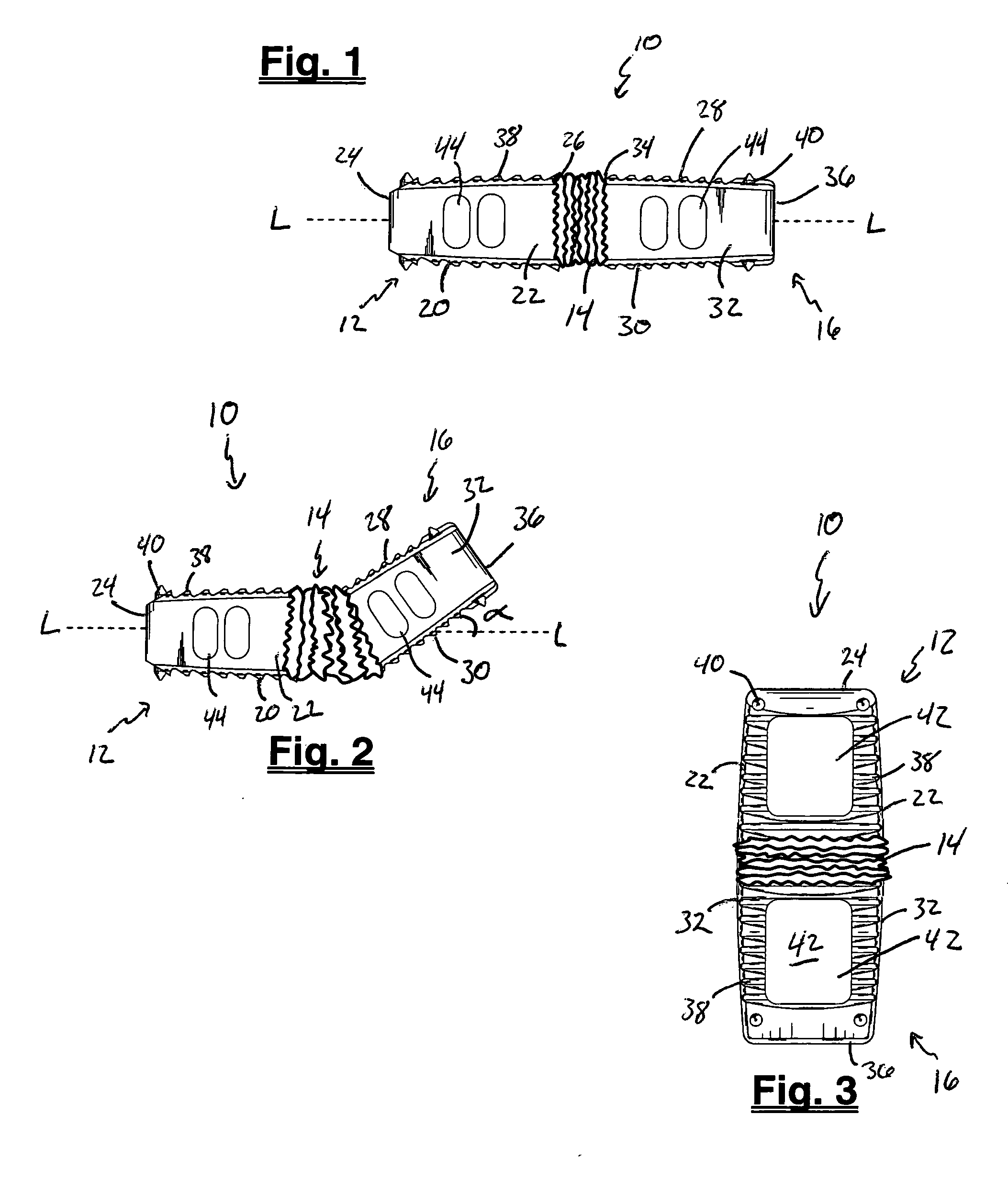
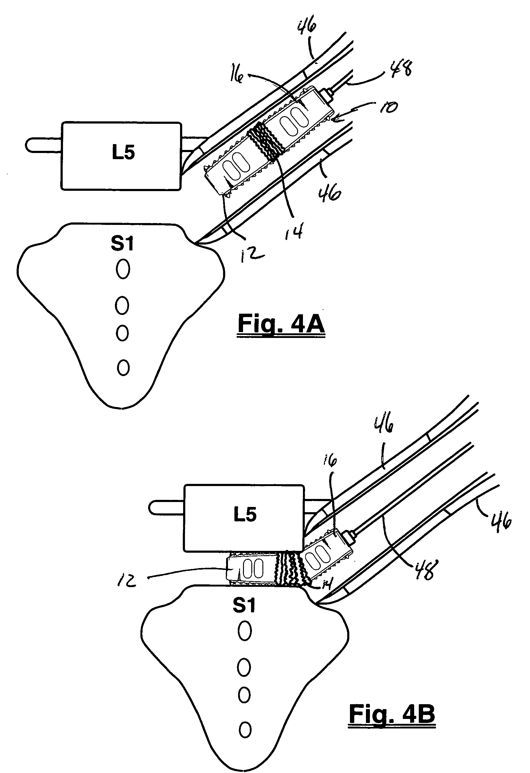
The present invention includes a spinal fusion system for performing spinal fusion between adjacent lumbar vertebrae, including an exemplary spinal fusion implant. In one embodiment, the implant has a generally rectangular shape, with a leading element, a trailing element. The leading element and the trailing element are connected via flexible element. The flexible element allows the trailing element to move relative to the leading element (or vice versa). Thus, trailing element (and / or leading element) may bend from a neutral position in which the trailing element (and / or leading element) is aligned with the longitudinal axis L to a biased position in which the trailing element (and / or the leading element) deviates from the longitudinal axis L. This flexibility allows the implant to adopt various temporary profiles that may be desirable, particularly during insertion. For example, when the operative corridor used to access the disc space is offset or angled relative to the plane of the disc space the implant may transition from the offset access trajectory to the disc space in stages (e.g. the leading element may transition before the trailing element), thus protecting the vertebral endplates during insertion. The flexible element should thus be flexible enough to allow the trailing element to bend appropriately without effecting the overall integrity and strength of the implant.
The flexible element permits the trailing element to move relative to the leading element as the leading element enters the disc space. In this manner, the longitudinal axis L of the implant is permitted to rotate into alignment with the disc space, despite the small height of the disc space relative to the length of the implant and any space constraints in the operative corridor and the implant may be advanced into the disc space without causing damage.

Problems solved by technology

When the surgical angle is less than optimal, the advancing implant may gouge or injure the vertebral endplate as it enters the intervertebral space.
This may have the undesirable effect of destabilizing the interbody fusion.

Method used


Image

  • Spinal Surgical Implant and Related Methods
  • Spinal Surgical Implant and Related Methods
  • Spinal Surgical Implant and Related Methods

Examples


Embodiment Construction

Illustrative embodiments of the invention are described below for the purposes of understanding the principles of the invention. No limitation of the scope of the invention is therefore intended. In the interest of clarity, not all features of an actual implementation are described in this specification. It will be appreciated that in the development of any such actual embodiment, numerous implementation-specific decisions must be made to achieve the developers' specific goals, such as compliance with system-related and business-related constraints, which will vary from one implementation to another. Moreover, it will be appreciated that such a development effort might be complex and time-consuming, but would nevertheless be a routine undertaking for those of ordinary skill in the art having the benefit of this disclosure. The invention disclosed herein boasts a variety of inventive features and components that warrant patent protection, both individually and in combination.

With ref...


PUM


Abstract

This invention relates generally to spine surgery and, in particular, to a surgical implant for separating adjacent spinal vertebrae.

Description

BACKGROUND OF THE INVENTIONI. Field of the InventionThis invention relates generally to spine surgery and, in particular, to a surgical implant for separating adjacent spinal vertebrae.II. Discussion of the Prior ArtThe spinal column is made up of individual vertebrae that provide support for the body and allow spinal movement. Between each vertebra sits a fibrocartilaginous disc that serves as a cushion and allows slight movement of the vertebrae. Spinal fusion procedures are common surgical techniques used to correct problems with displaced, damaged, or degenerated discs due to trauma, disease, or aging. Currently estimates suggest there are approximately 500,000 to 750,000 spinal fusion procedures performed each year in the United States. Generally, spinal fusion procedures involve removing the diseased or damaged disc and inserting one or more intervertebral implants into the resulting disc space. Introducing the intervertebral implant restores the height between adjacent verteb...

Claims


Application Information

Patent Timeline
IPC IPC(8): A61F2/44
CPCA61F2/447A61F2310/00179A61F2002/2835A61F2002/3008A61F2002/30462A61F2002/30466A61F2002/30492A61F2002/305A61F2002/30507A61F2002/30565A61F2002/30624A61F2002/30629A61F2002/30637A61F2002/30777A61F2002/30779A61F2002/30784A61F2002/30785A61F2002/30841A61F2002/30879A61F2002/30904A61F2002/30967A61F2002/4415A61F2002/4475A61F2002/448A61F2002/4485A61F2002/4628A61F2310/00023A61F2/4611A61F2002/30593A61F2/4425
Inventor RODGERS, W. BLAKECURRAN, MATTHEWARNOLD, BENJAMIN
Owner NUVASIVE
Learn More