
DRAM Control Method and the DRAM Controller Utilizing the Same

a dram controller and control method technology, applied in the direction of memory address/allocation/relocation, instruments, computing, etc., can solve the problems of serious degradation of dram performance and long time required for partial write requests

Active Publication Date: 2011-05-26
VIA TECH INC
View PDF5 Cites 6 Cited by
  • Summary
  • Abstract
  • Description
  • Claims
  • Application Information

AI Technical Summary

Benefits of technology

[0010]An exemplary embodiment of a DRAM control method utilized by a DRAM controller is provided, wherein the DRAM controller controls read and write operations of a DRAM and includes a storage unit, including: storing a first predetermined size of data, including data written into the DRAM in response to a previous partial write request, and store addresses of the first predetermined size of data in the DRAM into the storage unit; and in response to a read request, determining whether there exists any address in the store addresses equal to a read address of the read request, and reading data corresponding to the read address from the storage unit when there exists same address in the store addresses equal to the read address.
[0010]An exemplary embodiment of a DRAM control method utilized by a DRAM controller is provided, wherein the DRAM controller controls read and write operations of a DRAM and includes a storage unit, including: storing a first predetermined size of data, including data written into the DRAM in response to a previous partial write request, and store addresses of the first predetermined size of data in the DRAM into the storage unit; and in response to a read request, determining whether there exists any address in the store addresses equal to a read address of the read request, and reading data corresponding to the read address from the storage unit when there exists same address in the store addresses equal to the read address.

Problems solved by technology

Therefore, the time required for a partial write request is long.
When the DRAM controller receives multiple partial write requests within a short period of time, DRAM performance is seriously degraded.

Method used


Image

  • DRAM Control Method and the DRAM Controller Utilizing the Same
  • DRAM Control Method and the DRAM Controller Utilizing the Same
  • DRAM Control Method and the DRAM Controller Utilizing the Same

Examples


Embodiment Construction

[0016]The following description is of the best-contemplated mode of carrying out the invention. This description is made for the purpose of illustrating the general principles of the invention and should not be taken in a limiting sense. The scope of the invention is best determined by reference to the appended claims.

[0017]In the following paragraphs, some embodiments of the DRAM controller and DRAM control method are described and reference may be made to the figures. In the figures, the same symbols represent the same elements. Note that the description is made for the purpose of illustrating the concept of the invention and should not be taken in a limiting sense.

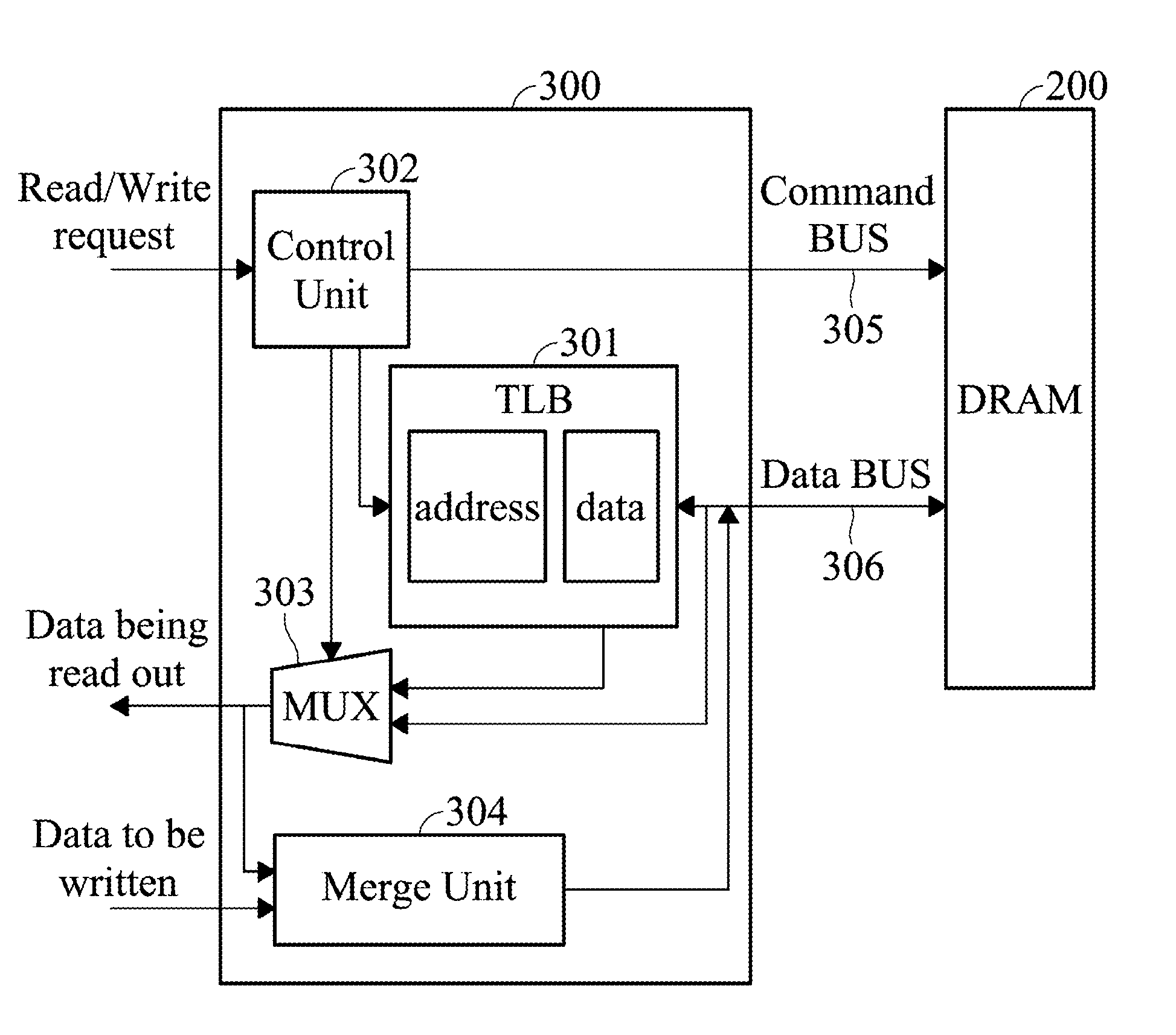
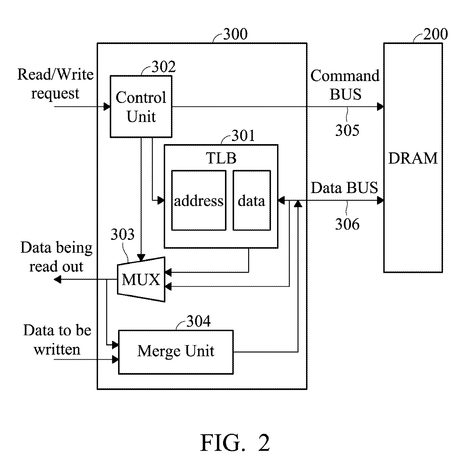
[0018]To begin, FIG. 2 shows a DRAM controller according to an embodiment of the invention.

[0019]As shown in FIG. 2, the DRAM controller 300 includes a Table Look aside Buffer (TLB) 301, a control unit 302, a multiplexing unit (MUX) 303 and a merge unit 304.

[0020]The DRAM controller 300 is coupled to the DRAM 200 via th...


PUM


Abstract

A Dynamic Random Access Memory (DRAM) controller for controlling read and write operations of a DRAM includes a storage unit and a control unit. The storage unit stores a first predetermined size of data including data written into the DRAM in response to a previous partial write request, and stores the corresponding store addresses of the first predetermined size of data in the DRAM. The control unit, in response to a read request, determines whether there exists any address in the store addresses equal to a read address of the read request, and read data corresponding to the read address from the storage unit when there exists same address in the store addresses equal to the read address.

Description

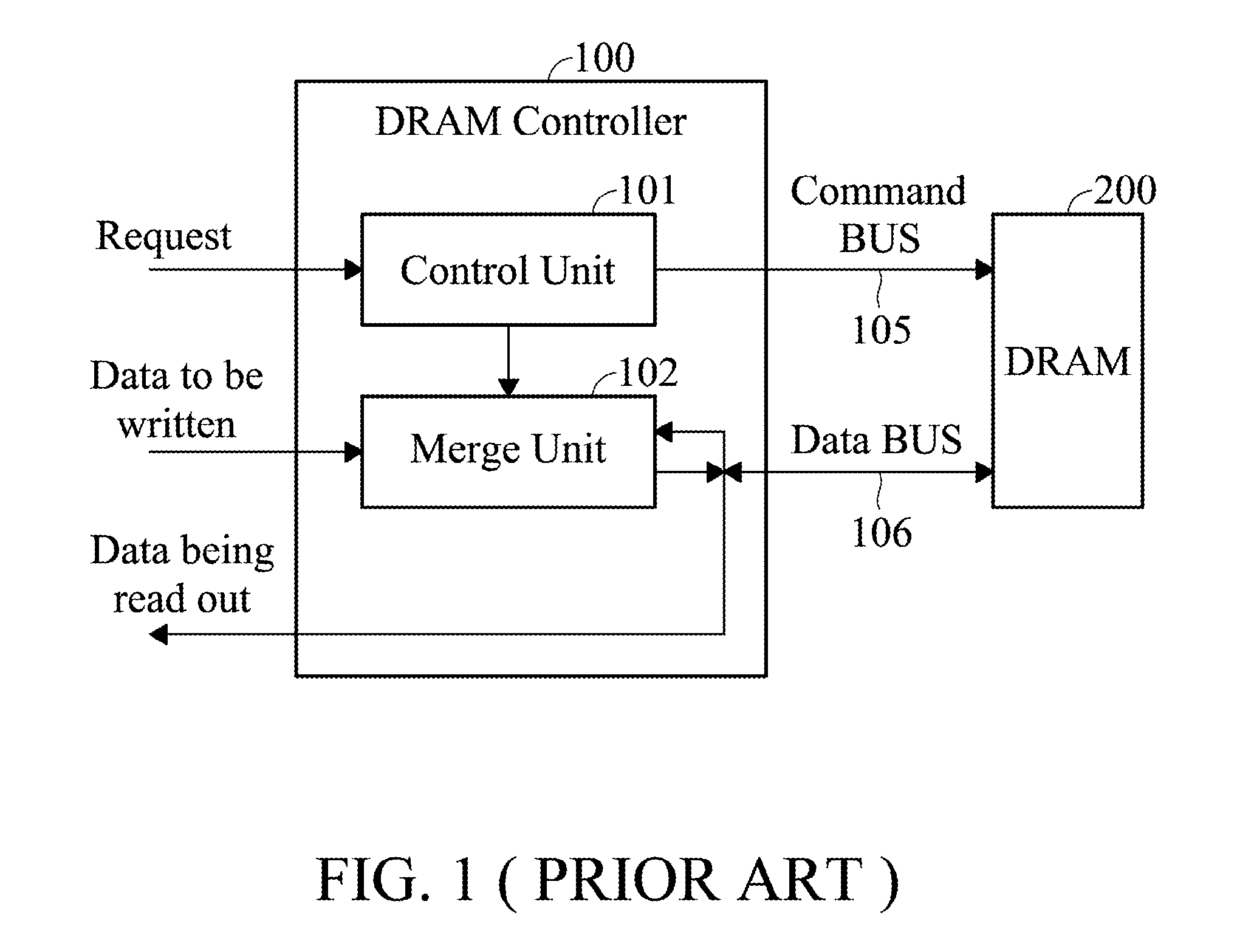
CROSS REFERENCE TO RELATED APPLICATIONS[0001]This Application claims priority of China Patent Application No. 200910224941.2, filed on Nov. 26, 2009, the entirety of which is incorporated by reference herein.BACKGROUND OF THE INVENTION[0002]1. Field of the Invention[0003]The invention relates to a Dynamic Random Access Memory (DRAM) controller and DRAM control method, and more particularly to a DRAM controller and DRAM control method capable of compensating for performance degradation due to a Read-Modify-Write (RWM) operation in response to a partial write request.[0004]2. Description of the Related Art[0005]Currently, Dynamic Random Access Memory (DRAM) is widely used for data storage. Generally, read / write operations are controlled by a DRAM controller. FIG. 1 is a block diagram showing a conventional DRAM controller. As shown in FIG. 1, the DRAM controller 100 includes a control unit 101 and a merge unit 102, coupled to the DRAM 200 through a command bus 105 and a data bus 106, ...

Claims


Application Information

Patent Timeline
Patent Type & Authority Applications(United States)
IPC IPC(8): G06F12/00G06F12/10
CPCG06F13/1673G06F12/1027
Inventor DING, JIE
Owner VIA TECH INC
Learn More