Flash memory storage system and method

a flash memory and storage system technology, applied in the field of flash memory storage system, can solve the problems of affecting the design and management of the memory system, the implementation of a second memory for caching, and the inability of the storage system to record a stream of incoming data transmitted to it at a higher writing rate,

Active Publication Date: 2007-03-15
WESTERN DIGITAL ISRAEL LTD
View PDF12 Cites 373 Cited by
  • Summary
  • Abstract
  • Description
  • Claims
  • Application Information

AI Technical Summary

Benefits of technology

[0032] Accordingly, it is a principal object of the present invention to overcome the disadvantages of prior art techniques used for employing a dedicated cache method while overcoming wear-out problems caused from frequently writing to the memory cells.
[0041] applying a first wear leveling technique within the first group of memory cells to evenly distribute wear of the first group of memory cells within themselves.
[0046] applying a second wear leveling technique within the second group of memory cells to evenly distribute wear of the second group of memory cells within themselves.
[0050] a mechanism for applying a first wear leveling technique within the first group of memory cells to evenly distribute wear of the first group of memory cells within themselves.

Problems solved by technology

Therefore, a storage system based on an MLC flash memory might not be capable of recording a stream of incoming data transmitted to it at a higher writing rate.
However, the implementation of a second memory for caching has its drawbacks.
Such implementation requires additional components for the cache memory and its control, and it complicates the design and management of the memory system.
Flash memory cells are known to wear out during use, i.e. the more write / erase cycles they go through, the more wear they suffer.
Therefore, according to Lee, memory cells allocated to the cache according to the dedicated cache method, will wear out much faster than the other memory cells, and might reach the end of their lifetime (i.e. the end of their useful functional capability) while the cells not used for the cache are still functioning well.
. . because instances of low density programming can cause more wear than instances of high density programming.”
Therefore, not only are the memory cells of the cache memory written more frequently and so tend to wear out more quickly, but also, according to the Lee patent, even under equal number of write / erase cycles—a memory cell configured to operate in SLC mode is worn out earlier than a memory cell configured to operate in MLC mode.
However, the main drawback of this approach is that the mixed cache method is much more complex to accomplish and handle, since a real-time mode switching management is required.

Method used


Image

  • Flash memory storage system and method
  • Flash memory storage system and method

Examples


Embodiment Construction

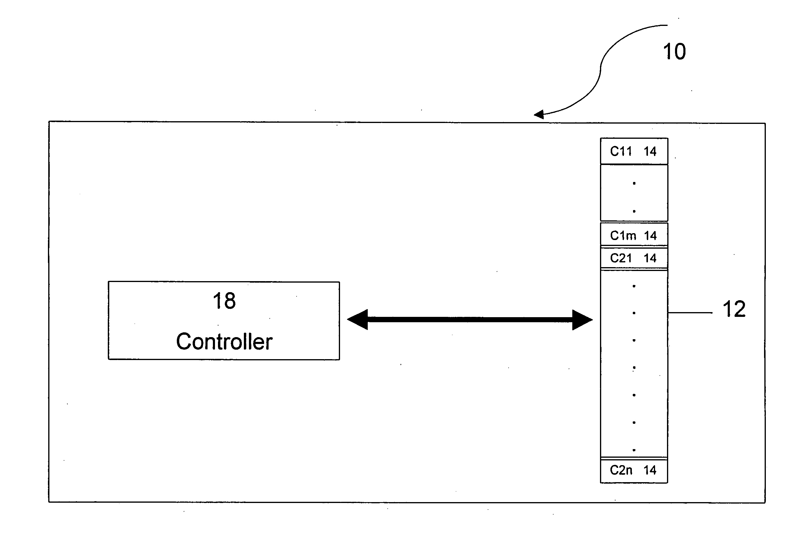
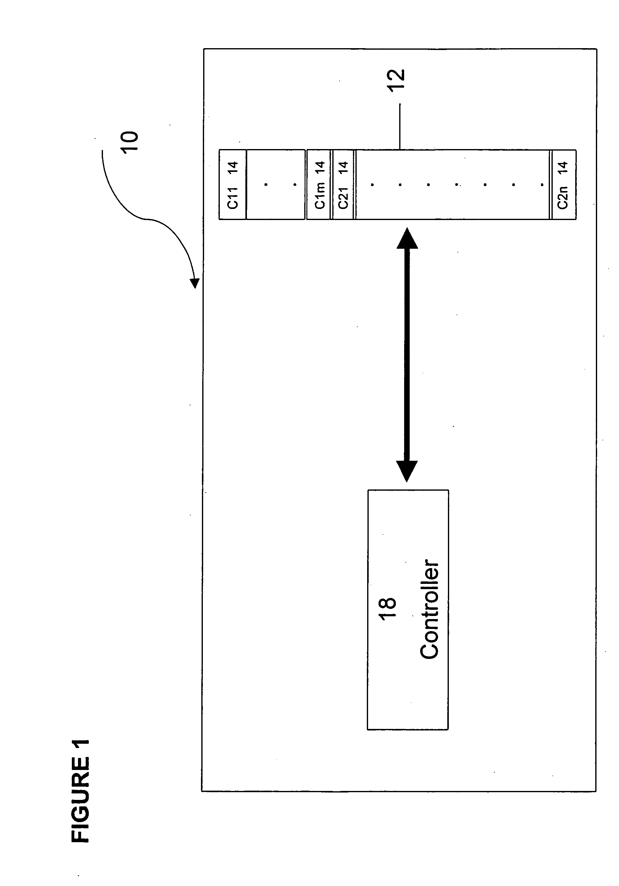
[0054] The present invention discloses an innovative flash memory storage system employing a dedicated cache method while overcoming wear-out problems caused from frequently writing to the memory cells.

[0055] The proposed flash memory storage system includes a flash memory array containing two groups of memory cells. A controller is provided to control the flash memory array by operating a first group of memory cells in SLC mode and a second group of memory cells in MLC mode. Memory cells operating in MLC mode (MLC cells) contain a larger number of bits than SLC cells, such that the bits of the two groups of memory cells are disjoint (i.e. the two groups of memory cells do not overlap, have no element in common, etc.). Informally, two groups are disjoint if there can be no object that is an instance of both groups.

[0056] According to the dedicated cache method, a specific portion of the memory cells is always allocated to operate in SLC mode, while other memory cells are allocated...


PUM


Abstract

A flash memory storage system includes a memory array containing a plurality of memory cells and a controller for controlling the flash memory array. The controller dedicates a first group of memory cells to operate with a first number of bits per cell and a second, separate group of memory cells to operate with a second number of bits per cell. A mechanism is provided to apply wear leveling techniques separately to the two groups of cells to evenly wear out the memory cells.

Description

CROSS-REFERENCE TO RELATED APPLICATIONS [0001] This patent application claims the benefit of U.S. Provisional Patent Application No. 60 / 715,391, filed Sep. 9, 2005.FIELD OF THE INVENTION [0002] The present invention relates generally to a flash memory storage system. More particularly, the present invention relates to a flash memory storage system including a cache memory mechanism capable of storing multiple bits per memory cell. BACKGROUND OF THE INVENTION [0003] A flash memory system implemented as a Multi-Level Cell (MLC) flash memory is provided for storing more than one bit of data on each memory cell. The writing of data into an MLC flash memory is typically slower than the writing of data into a Single-Level Cell (SLC) flash memory that stores only one bit of data per cell. Therefore, a storage system based on an MLC flash memory might not be capable of recording a stream of incoming data transmitted to it at a higher writing rate. [0004] Typically in cases where data is pro...

Claims


Application Information

Patent Timeline
Patent Type & Authority Applications(United States)
IPC IPC(8): G06F12/00
CPCG06F12/0246G06F12/0866G06F2212/2022G11C2211/5641G11C11/5621G11C16/349G11C16/3495G06F2212/7211G06F12/00G06F13/16
Inventor LASSER, MENAHEMMURIN, MARKEYAL, ARIK
Owner WESTERN DIGITAL ISRAEL LTD
Why Eureka
Try Eureka