Measuring and dispensing container

a technology for measuring containers and containers, applied in the direction of liquid transferring devices, movable measuring chambers, instruments, etc., can solve the problems of safety hazards caused by foaming, and achieve the effects of avoiding turbulence, minimizing foaming risk, and minimizing foaming risk

Active Publication Date: 2011-06-02
JENNINGS ROBERT M +1
View PDF11 Cites 22 Cited by
  • Summary
  • Abstract
  • Description
  • Claims
  • Application Information

AI Technical Summary

Benefits of technology

[0013]It is also preferred that the outlet from the conduit into the measuring and dispensing chamber is located and oriented in such a way as to avoid turbulence in the liquid being introduced into the measuring and dispensing chamber so as to minimize the risk of foaming. This can be accomplished by releasing the liquid close to and directed almost parallel to a surface down which it can flow. By directing liquid entering the measuring and dispensing chamber in this way so as to run smoothly down a wall rather than being released into a void, one is minimizing the risk of foaming in the same way that one does when beer or champagne are poured into a tilted glass.
[0014]In order further to assist in ensuring that the correct quantity of liquid is dispensed from the measuring and dispensing chamber, it is preferred that the axis of dispensing outlet is parallel with the front wall of the measuring and dispensing chamber and that at least at one point on the edge of the outlet, there is a flush surface of the with front wall of the measuring and dispensing chamber. the axis of the dispensing outlet being oriented parallel to that wall and located at the point of intersection of that wall and the upper wall of the measuring and dispensing chamber. Furthermore it is often preferred that the front wall of the measuring and dispensing chamber is set at an angle to the vertical so as to make it easier to ensure that all liquid in the measuring and dispensing chamber can be poured out without the need completely to rotate the container by at least 90° as is required where the front wall is vertical and the outlet provided in the front wall or even more if the outlet is located in the top of the container to make sure that it is fully drained These features assist in making sure that none of the liquid that has been transferred to the measuring and dispensing chamber is retained in it when the chamber is emptied.

Problems solved by technology

In addition to minimizing the risk of foaming and thus of inaccurate measurement of the amount of liquid transferred to the measuring and dispensing chamber, the direction of the incoming liquid down a wall also avoids the risk of liquid splashing out of the measuring and dispensing chamber, which splashing can create a safety hazard.

Method used


Image

  • Measuring and dispensing container
  • Measuring and dispensing container
  • Measuring and dispensing container

Examples


Embodiment Construction

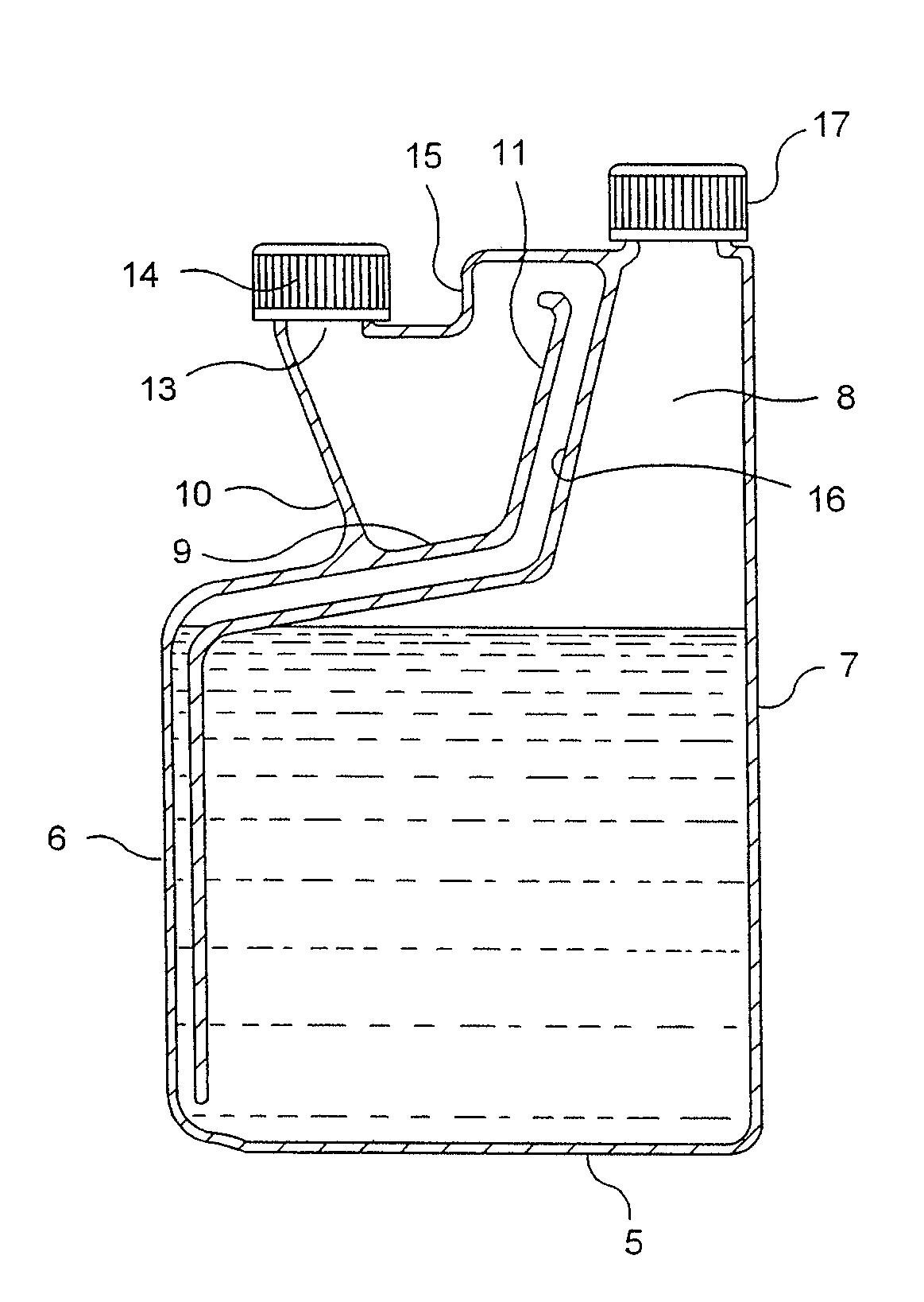
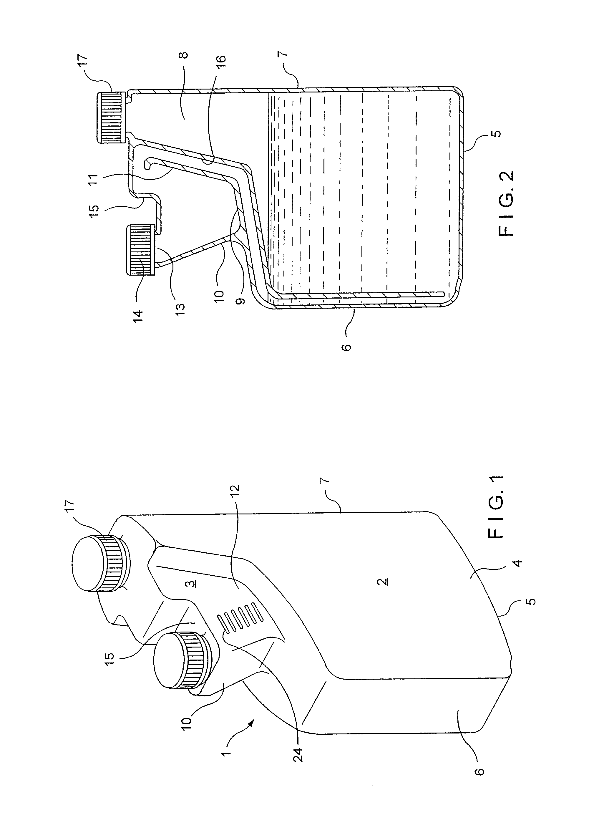
[0038]Referring now to the drawings, FIG. 1 is a perspective view of a container of the invention which is used for storing, measuring, and dispensing a predetermined amount of liquid. The container 1 includes a reservoir chamber 2 and a measuring and dispensing chamber 3 in fluid communication therewith in a manner to be described hereinafter. The reservoir chamber 2 is defined by side walls 4 (only one side wall 4 being shown in the drawings), a bottom 5, a front wall 6, and a rear wall 7. It will be appreciated that, although only one side wall 4 is shown, the opposite side wall of the container is a mirror image thereof.

[0039]The top of the reservoir chamber is a more complex configuration and incorporates not only the measuring and dispensing chamber but also a filling passage 8 in a manner now to be described in greater detail. The measuring and dispensing chamber 3 is located above the main body of the reservoir chamber 2 and forwardly of the filling passage 8. The measuring ...


PUM


Abstract

A container for measuring a predetermined amount of liquid and dispensing that measured amount. The container includes a reservoir chamber, a measuring and dispensing chamber, and a conduit or tube for transferring liquid from the reservoir chamber to the measuring and dispensing chamber. The reservoir chamber has flexible walls which can be squeezed to drive liquid from the reservoir chamber into the measuring chamber. The passage from the reservoir to the measuring and dispensing chamber is configured and its outlet arranged so that liquid entering the chamber flows down a wall thereof.

Description

RELATED APPLICATION[0001]This is a continuation-in-part of application Ser. No. 11 / 643,341 filed on Dec. 21, 2006, the contents of which are incorporated herein by reference.BACKGROUND OF THE INVENTION[0002]Measuring and dispensing containers having a reservoir or storage chamber and a measuring chamber arranged to receive a predetermined amount of liquid from the reservoir chamber and subsequently dispense that predetermined amount of liquid are known. Examples of such measuring and dispensing chambers are disclosed in U.S. Pat. Nos. 4,079,859; 4,298,038; 4,646,948; 4,893,732; and 6,290,102[0003]U.S. Pat. No. 4,646,948 discloses a number of embodiments of containers in which liquid is poured from a reservoir chamber to a measuring chamber. When the desired amount of liquid has accumulated in the measuring chamber, surplus liquid is returned to the reservoir chamber by controlled tilting of the container and then the measured accumulation is dispensed from the measuring chamber.[000...

Claims


Application Information

Patent Timeline
Patent Type & Authority Applications(United States)
IPC IPC(8): B65D37/00
CPCB65D1/0223B65D23/00G01F11/286G01F11/262B65D25/56
Inventor JENNINGS, ROBERT M.JENNINGS, DAVID A.
Owner JENNINGS ROBERT M
Why Eureka
Try Eureka