
Sliding roof sunshade assembly

a technology for sliding roofs and sunshade assemblies, which is applied in the direction of roofs, superstructure subunits, mechanical equipment, etc., can solve the problems of reducing the clear width of the roof opening, disturbing, and giving the vehicle occupants the impression of a smaller roof opening

Inactive Publication Date: 2011-06-02
ROOF SYST GERMANY
View PDF4 Cites 0 Cited by
  • Summary
  • Abstract
  • Description
  • Claims
  • Application Information

AI Technical Summary

Benefits of technology

In one example, an elastic coupling is provided between the front end of the sunshade element and the drive element. The elastic coupling makes it possible for the tolerances in the movement path of the sunshade element to be compensated by virtue of the drive element, after an end setting is reached, being moved onward into a position in which it is ensured, taking into consideration all the tolerances, that the sunshade element has reached its closed position. The end setting of the drive element is the position in which, without inaccuracies in the system, the sunshade element has exactly reached the closed position. The sunshade element pauses in its closed position when the sunshade element has reached the latter. The further movement of the drive element is absorbed exclusively by the elastic intermediate element. In this way, it is possible for a tolerance path in the region of approximately 10 mm to be compensated without problems.
Since it is ensured that the front end of the sunshade element ends exactly in the closed position during every closing process of the latter, the clear width of the roof opening need not artificially be reduced in size by a lining in order to eliminate the possibility of a gap remaining between the front end of the sunshade element and the edge of the roof opening.
Here, the bow is preferably fixedly fastened to the intermediate element such that the drive element can move relative to the bow counter to the resistance of the intermediate element. It is advantageous for only a linear movement in the movement direction but no movement perpendicular to said direction to be possible between the bow and the drive element, in order that exact positioning of the drive element, of the bow and of the front end of the sunshade element is possible.
Here, for precise positioning, it is advantageous for the front end of the sunshade element, the intermediate element, and the bow to be arranged substantially linearly one behind the other. In this way, a force transmitted via the drive element can be introduced into the intermediate element without force components perpendicular to the movement direction.

Problems solved by technology

Here, even a small gap between a front end of the sunshade element and the edge of the roof opening, through which blinding solar radiation can still pass, can prove to be disturbing.
The disadvantage of this solution is that the clear width of the roof opening is reduced, which gives the vehicle occupants the impression that the roof opening is smaller.

Method used


Image

  • Sliding roof sunshade assembly
  • Sliding roof sunshade assembly
  • Sliding roof sunshade assembly

Examples


first embodiment

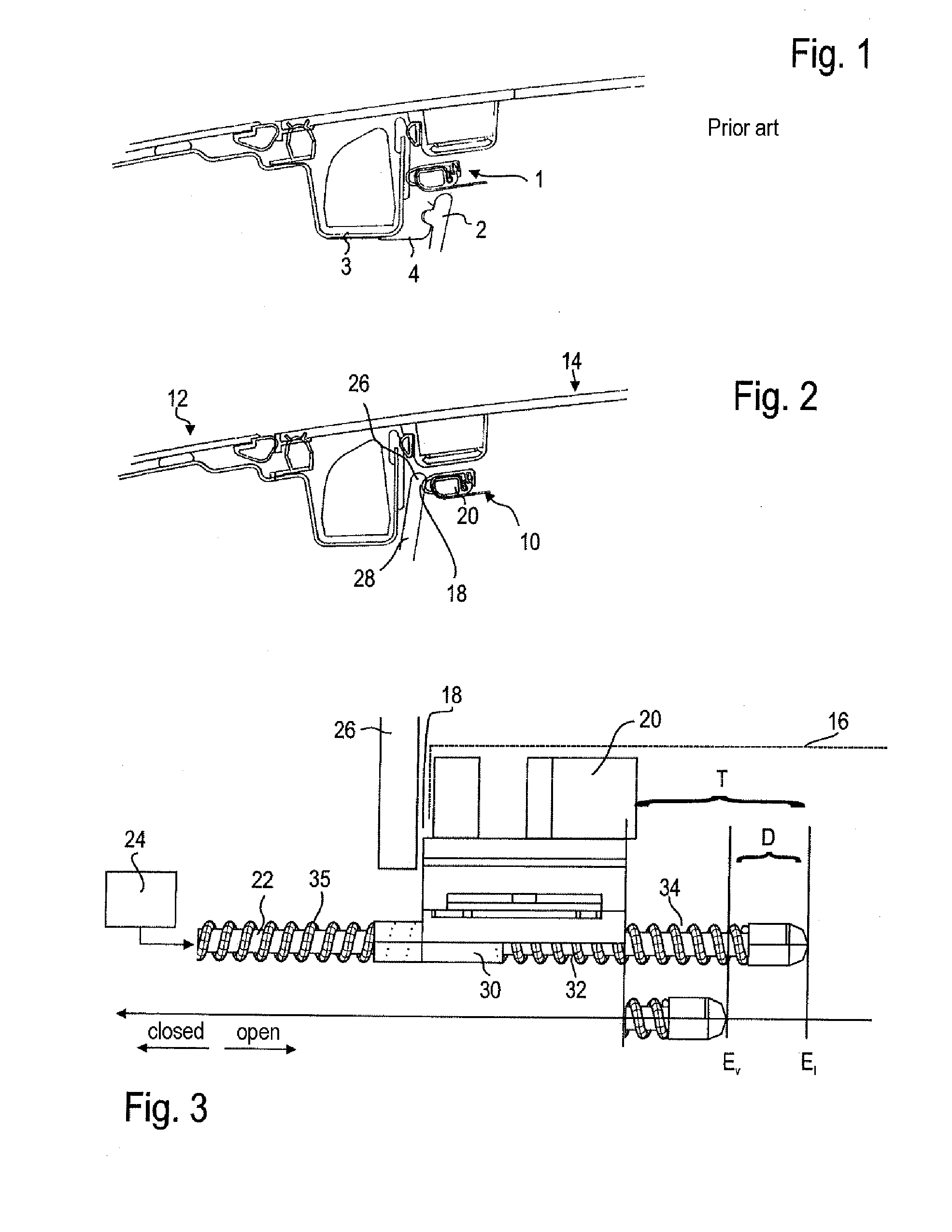
In the first embodiment shown in FIG. 3, the bow 20 is connected, in the region of the front end 18 of the sunshade element 16 (which is merely indicated here), to the drive element 22 in such a way as to be mounted linearly movably with respect thereto. In this case, the drive element 22 is a cable which is guided to be resistant to tension and rigid in compression.

The bow 20 has a fastening section 30 which engages around the drive element 22 and which is fastened to an elastic intermediate element 32, which is designed as a spiral spring. The elastic intermediate element 32 in turn extends between the fastening section 30 on the bow 20 and a stop 34 which is fixed to the drive element, to which stop 34 said elastic intermediate element 32 is likewise fastened. The bow 20 can be moved along the drive element 22 counter to the spring force of the elastic intermediate element 32, in particular in the direction of the stop 34, that is to say to the right in FIG. 3.

Here, the bow 20 an...

second embodiment

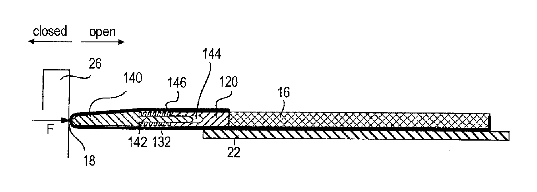
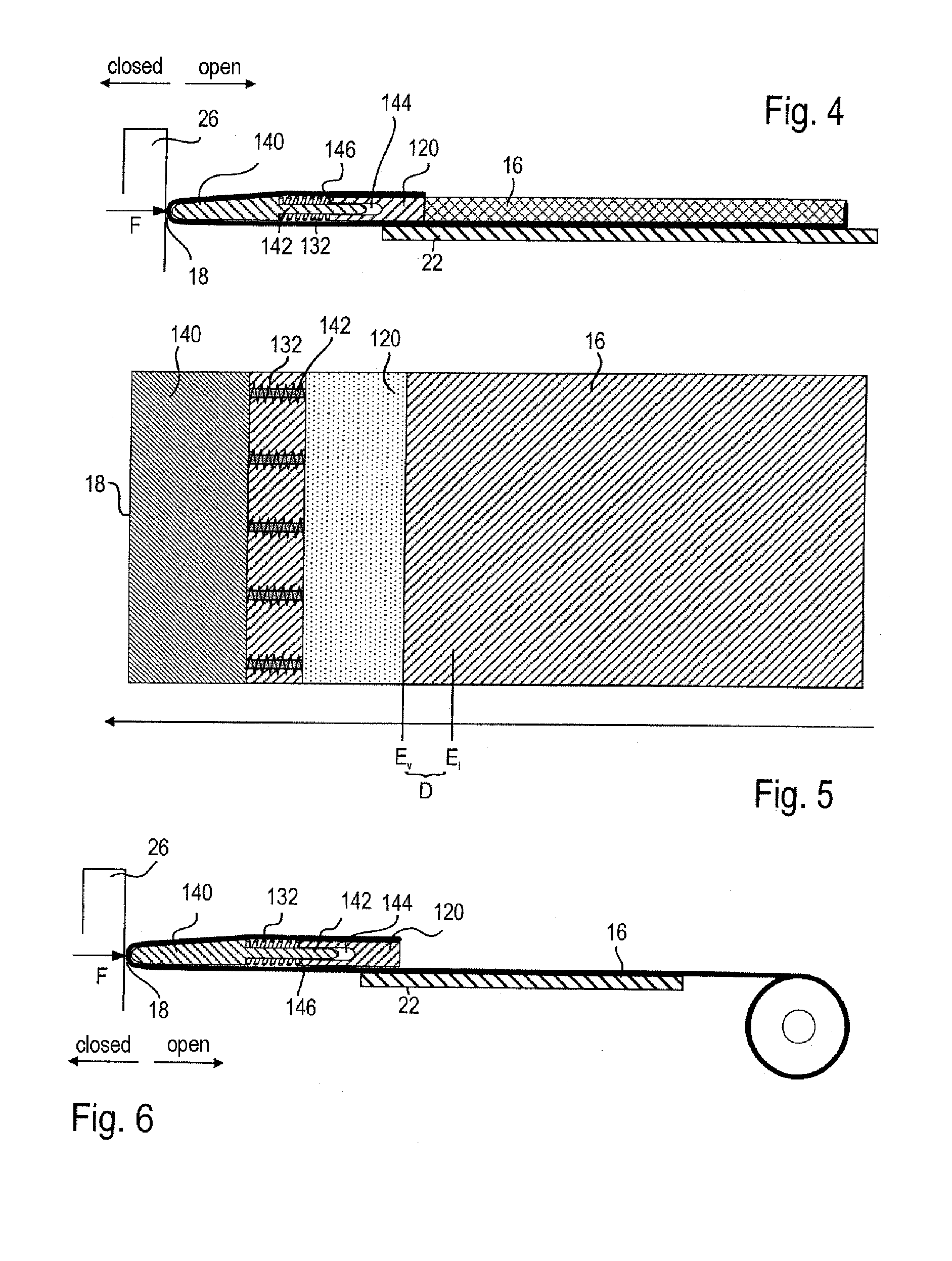
FIGS. 4 to 7 show a second embodiment in which an elastic intermediate element 132 is arranged between the front end 18 of the sunshade element 16 and a bow 120.

The sunshade element 16 has, at its front end 18, a closure element 140 which is designed as a rigid component which extends over the entire width of the sunshade element 16. The closure element 140 and the bow 120 are designed so as to be movable relative to one another. In this case, the drive element 22 is fixedly connected to the bow 120, such that the latter is movable neither relative to the body of the sunshade element 16 nor relative to the drive element 22.

A plurality of elastic intermediate elements 132 are provided, in this case five, which are arranged adjacent to one another so as to be distributed uniformly over the width of the sunshade element 16, as shown in FIG. 5. The intermediate elements 132 are all arranged between the closure element 140 and the bow 120.

The closure element 140 and the bow 120 are conne...


PUM


Abstract

A sliding roof sunshade assembly for a vehicle has a sunshade element which can be moved in opening direction and a closing direction. The sunshade element has a bow at a free front end. At least one force-transmitting drive element is connected to the bow and to a drive in order to move the sunshade element into a closed setting, with the front end of the sunshade element assuming a predetermined closed position in the closed setting. At least one elastic intermediate element is arranged in a force flow between the drive and the front end of the sunshade element. Once the front end of the sunshade element has reached the closed position, the drive moves the drive element onward into a predetermined end setting in which the intermediate element is elastically deformed. The predetermined end setting corresponds to a position in which the elastic intermediate element is compressed by an amount within a predetermined tolerance path.

Description

RELATED APPLICATIONThis application claims priority to European Application No. 09014901, which was filed Dec. 1, 2009.FIELD OF THE INVENTIONThe invention relates to a sliding roof sunshade assembly for a vehicle.BACKGROUNDAn opening which can be opened up by a sliding roof, or possibly also an opening which is closed off by a glass roof, in a vehicle roof is usually provided with a sunshade element which, in order to provide protection from solar radiation, can be moved by the vehicle occupants such that it fully or partially covers the opening or the glass roof on the inside. Such protection from the sun is also important because incident solar radiation can blind the driver. Here, even a small gap between a front end of the sunshade element and the edge of the roof opening, through which blinding solar radiation can still pass, can prove to be disturbing. It is therefore desirable for the front end of the sunshade element, in its closed position, to completely cover the front par...

Claims


Application Information

Patent Timeline
Patent Type & Authority Applications(United States)
IPC IPC(8): B60J7/02
CPCB60J7/003B60J7/0015
Inventor GRIMM, RAINERBOEHM, HORST
Owner ROOF SYST GERMANY
Learn More