
Thermal printer

a printer and thermal head technology, applied in the direction of printing, power drive mechanisms, instruments, etc., can solve the problems of lowering the printing quality, increasing the load of the motor driving the platen roller, and unable to obtain a proper printing density, so as to enhance the positioning precision between the platen roller and the thermal head

Inactive Publication Date: 2011-06-02
SEIKO INSTR INC
View PDF6 Cites 14 Cited by
  • Summary
  • Abstract
  • Description
  • Claims
  • Application Information

AI Technical Summary

Benefits of technology

[0038]Therefore, the present invention has been made in view of the above-mentioned circumstances, and has an object to provide a thermal printer in which a positioning precision between a platen roller and a thermal head is enhanced, thereby being capable of positively arranging and providing a heating element within a heating element allowable range.
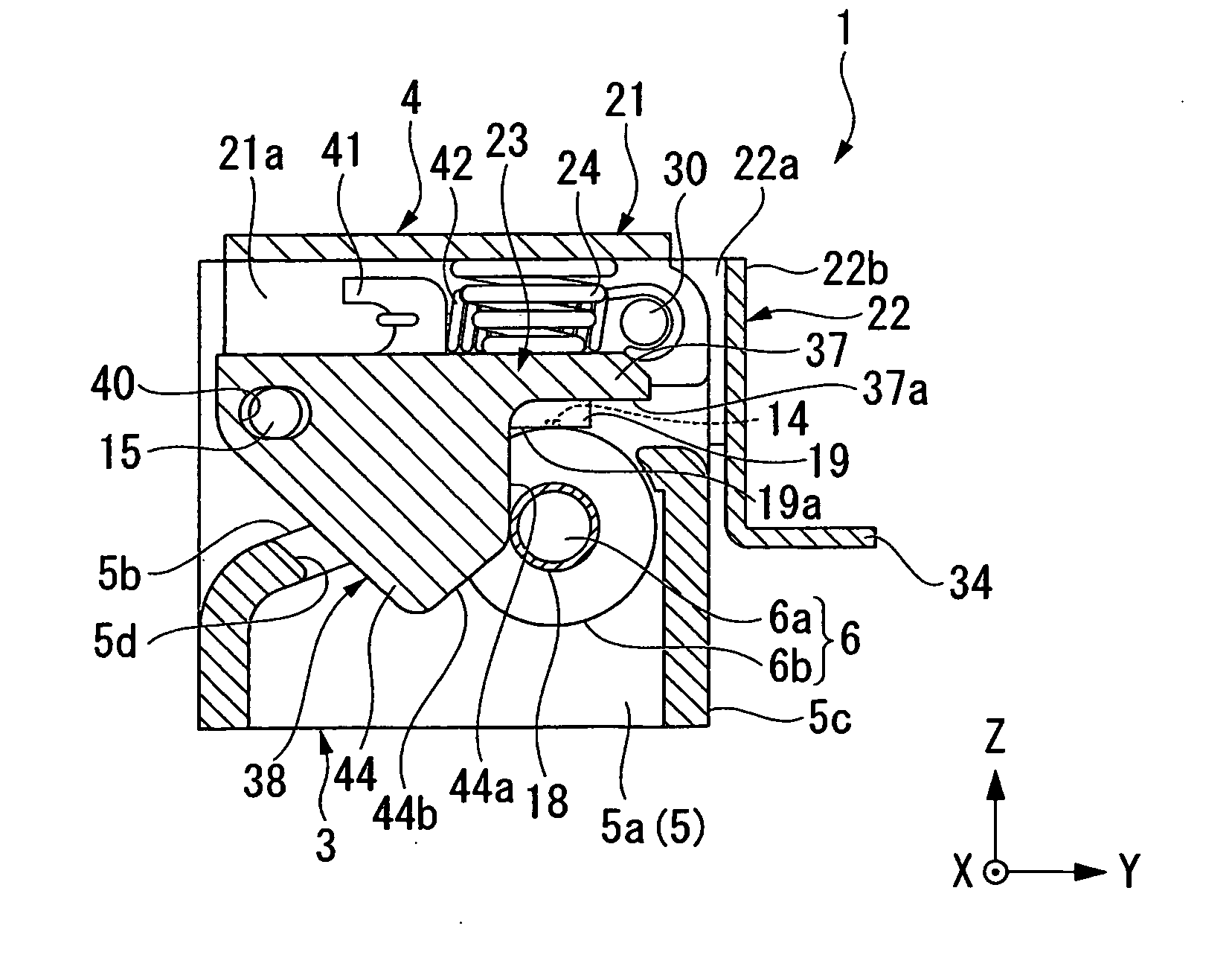
[0060]In other words, the head surface of the thermal head is brought into pressure contact with the platen roller by the first urging means, and the regulating portion abuts on the platen roller by the second urging means. As a result, while keeping a state in which a relative position among the platen roller, the regulating portion, and the thermal head falls within the heating element allowable range so that a satisfactory printing quality may be obtained, the positioning of the platen roller and the heating elements of the thermal head may be positively carried out.
[0062]According to the structure, as the head support member conducts a slide movement along the first direction, there is no need to provide a separate moving mechanism. Owing to this, the structure may be simplified, and also the reduction of the manufacturing cost may be achieved.
[0063]According to the present invention, the position between the platen roller and the thermal head is determined with the regulating portion being reference. As a result, the influences of the conditions (1) and (2), which are conventionally identified as problems, and become large tolerance factors, may be eliminated, and further, in the positional relationship between the platen roller and the thermal head, the heating element may be positively positioned within the heating element allowable range. Owing to this, even in a case where a plurality of kinds of the recording paper having different thicknesses and stiffnesses are used, the heating element may be disposed within the heating element with high precision, thereby being capable of printing with a satisfactory printing quality.
[0064]Further, as described above, the guide portion, which guides the regulating portion so as to abut on the platen roller, is formed in the head support member, and hence, the head support member may be moved smoothly along the guide portion in the mounting operation. As a result, when the regulating portion and the platen roller are abutted on each other, the mounting operation of the detachable unit is free from being interrupted, thereby being capable of quickly mounting the detachable unit to the main body unit.

Problems solved by technology

In a case where the heating element 101 does not exist within the allowable range L1 of the heating element, there is a fear in that heat of the heating element 101 may not sufficiently transmit to the recording paper P, resulting in occurring a problem of lowering a printing quality, such as being not able to obtain a proper printing density.
However, if the contact pressure increases, it leads to an increase of a motor load of a motor for driving the platen roller 104.
However, within a tendency of achieving downsizing in recent years, positioning precision of the heating element 101 with respect to the platen roller 104 becomes insufficient by the conventional method.
However, even if the increase of the facility cost is accepted to reduce the tolerances of the conditions (3) to (5), there are large tolerance influences generated in the conditions (1) and (2).

Method used


Image

  • Thermal printer
  • Thermal printer
  • Thermal printer

Examples


Embodiment Construction

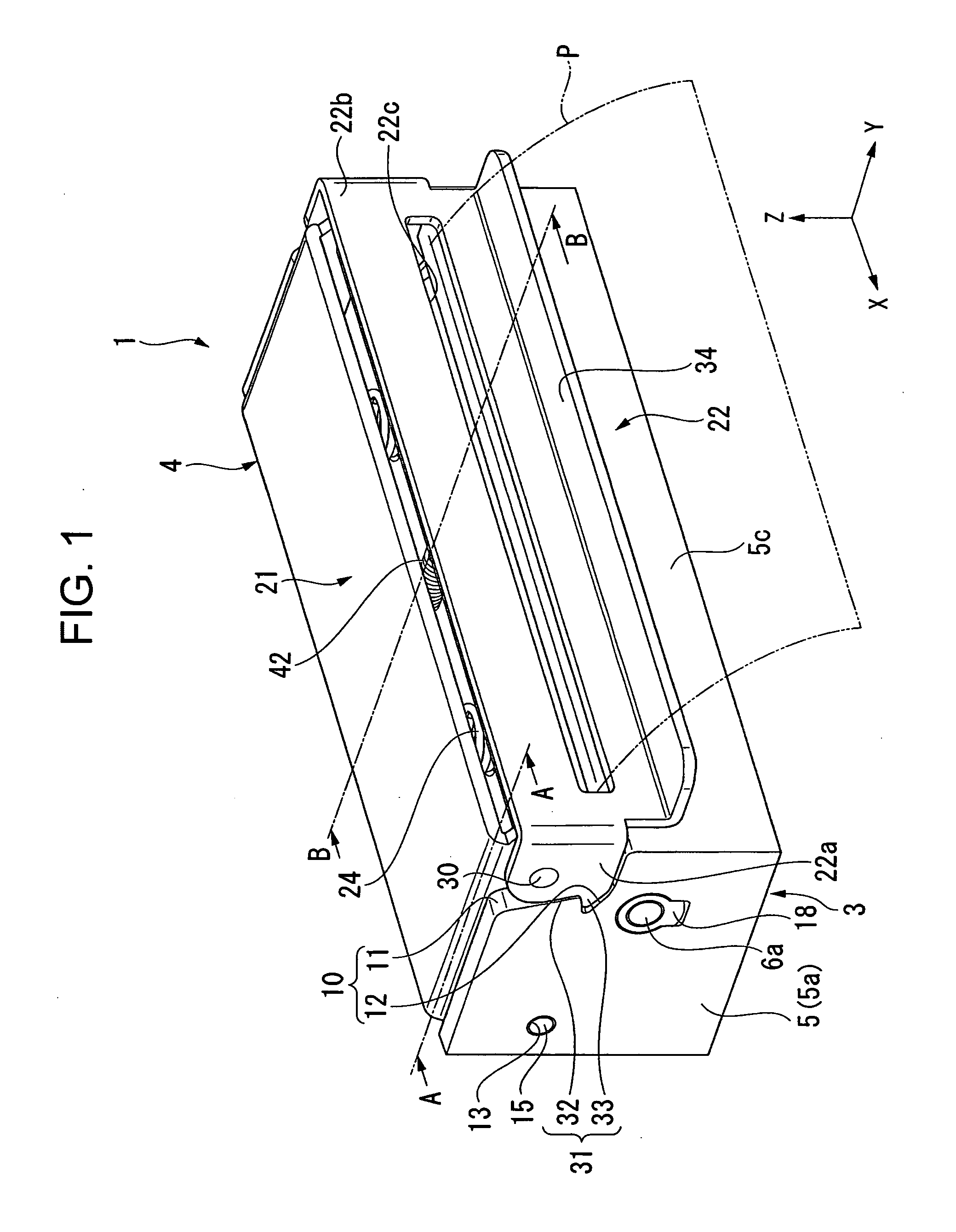
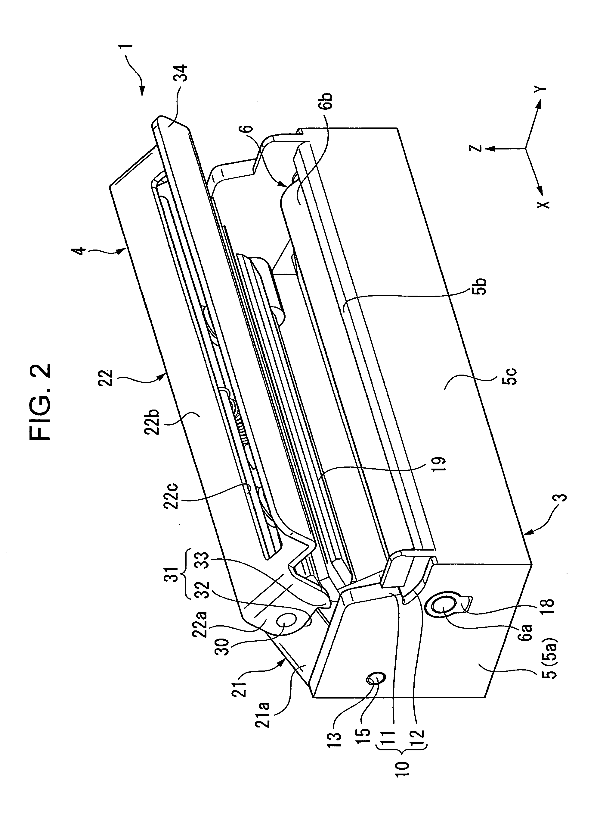
[0088]Hereinafter, embodiments of the present invention are described with reference to the drawings. In the following description, description is made of a head-open type thermal printer having such a structure that, a main body unit, to which a platen roller is mounted, is provided to a chassis side into which recording paper wound into a roll is received, and a cover unit, onto which a thermal head is mounted, is provided to a cover side, which allows an opening portion of the chassis to be openable and closable.

[0089]FIG. 1 and FIG. 2 are perspective views of a thermal printer according to the present invention, in which FIG. 1 illustrates a mounting state of the cover unit, and FIG. 2 illustrates a non-mounting state of the cover unit. Further, FIG. 3 is a side view of the thermal printer for illustrating the mounting state of the cover unit, FIG. 4 is a sectional view taken along the line A-A of FIG. 1, and FIG. 5 is a sectional view taken along the line B-B of FIG. 1. It shou...


PUM


Abstract

Provided is a thermal printer in which positioning precision between a platen roller and a thermal head is enhanced, thereby being capable of positively arranging heating elements within a heating element allowable range. A positioning mechanism (38) includes: a through-hole (40) which allows a head support member (23) to be movable with respect to a detachable frame (21); a regulating surface (44a) formed in the head support member (23), an elastic member (42) for urging the head support member (23) so that the regulating surface (44a) is abutted to a bearing (18) of the platen roller (6); and a guide portion (44b), which is formed in the head support member (23), for guiding the head support member (23) by moving the head support member along the through-hole (40) in association with a mounting operation of a cover unit (4) while sliding with the bearing (18) so that the regulating surface (44a) abuts the bearing (18), and the regulating surface (44a) is formed in a flat surface, and a normal line direction of the regulating surface (44a) coincides with a direction perpendicular to an axial direction of the platen roller (6) within a plane which is parallel with a head surface 19a of a thermal head (19).

Description

BACKGROUND OF THE INVENTION[0001]1. Field of the Invention[0002]The present invention relates to a thermal printer which performs printing various kinds of information on recording paper pulled out from roll paper.[0003]2. Description of the Related Art[0004]The thermal printer is a printer having such a structure that a particular recording paper (heat-sensitive paper), which develops color by being applied with heat, is sandwiched between a platen roller and a thermal head, and while the recording paper is being fed through rotation of the platen roller, a printing surface (heat-sensitive surface) of the recording paper is heated by a heating element of the thermal head to be developed color, thereby performing printing. As this type of the thermal printer, for example, there is known a head-open type thermal printer, which is incorporated into a cash resister or the like to be used for printing a receipt, etc. (for example, refer to Japanese Patent Application Laid-open No. 2000-...

Claims


Application Information

Patent Timeline
IPC IPC(8): B41J2/325
CPCB41J25/312B41J2/32
Inventor TAKAHASHI, MASANORI
Owner SEIKO INSTR INC
Learn More