Method for transmitting data in multiple antenna system

Inactive Publication Date: 2011-06-02
LG ELECTRONICS INC
View PDF25 Cites 71 Cited by
  • Summary
  • Abstract
  • Description
  • Claims
  • Application Information

AI Technical Summary

Benefits of technology

[0010]According to the present invention, a scheduling gain for opportunistic beamforming and a throughput obtained by channel-dependent precoding can be m

Problems solved by technology

The increase of the codebook set along with the increase of the number of antennas results in the increase

Method used


Image

  • Method for transmitting data in multiple antenna system
  • Method for transmitting data in multiple antenna system
  • Method for transmitting data in multiple antenna system

Examples


Embodiment Construction

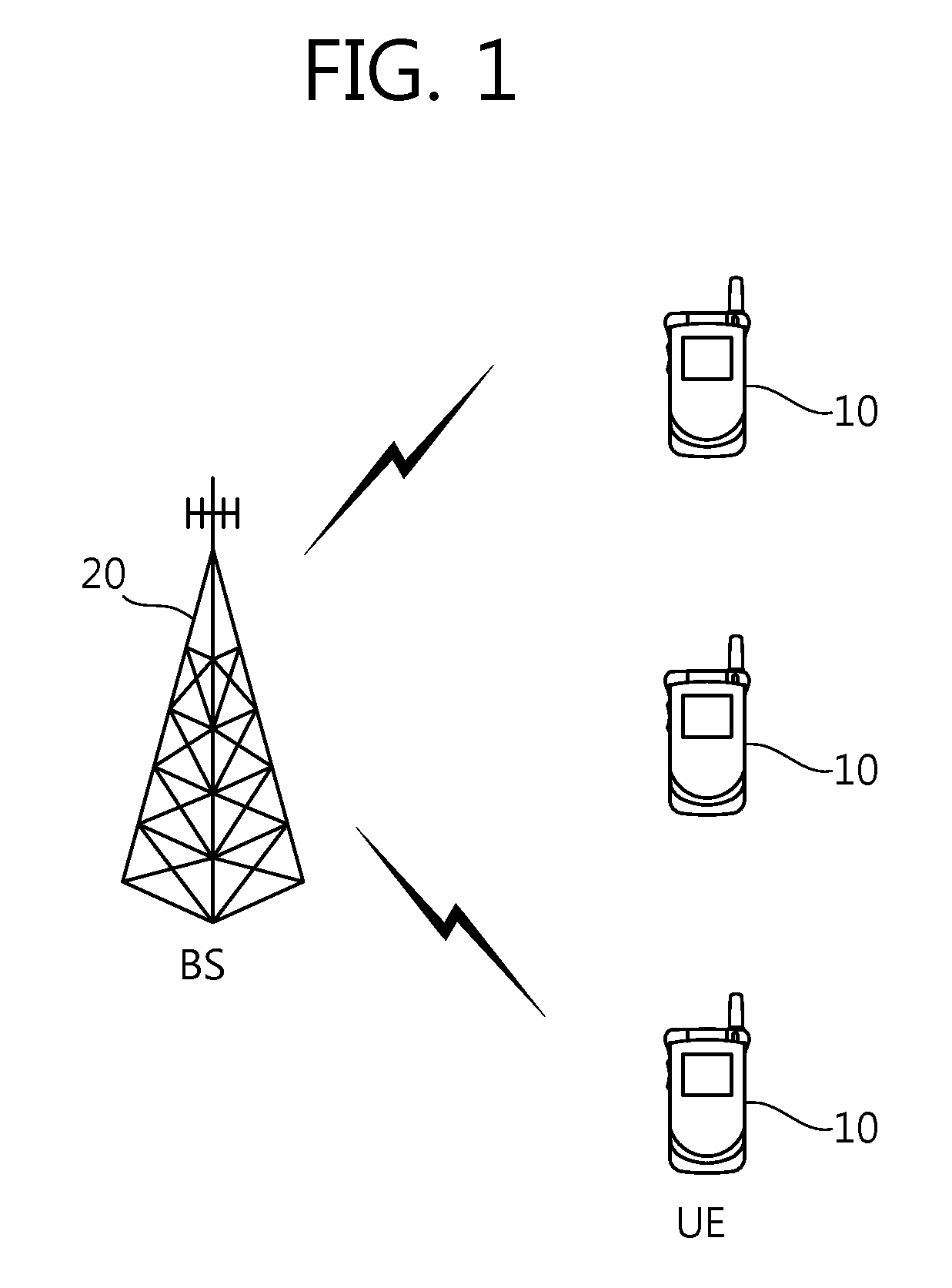
[0015]FIG. 1 shows a wireless communication system. The wireless communication system can be widely deployed to provide a variety of communication services, such as voices, packet data, etc.

[0016]Referring to FIG. 1, the wireless communication system includes at least one user equipment (UE) 10 and a base station (BS) 20. The UE 10 may be fixed or mobile, and may be referred to as another terminology, such as a mobile station (MS), a user terminal (UT), a subscriber station (SS), a wireless device, etc. The BS 20 is generally a fixed station that communicates with the UE 10 and may be referred to as another terminology, such as a node-B, a base transceiver system (BTS), an access point, etc. There are one or more cells within the coverage of the BS 20.

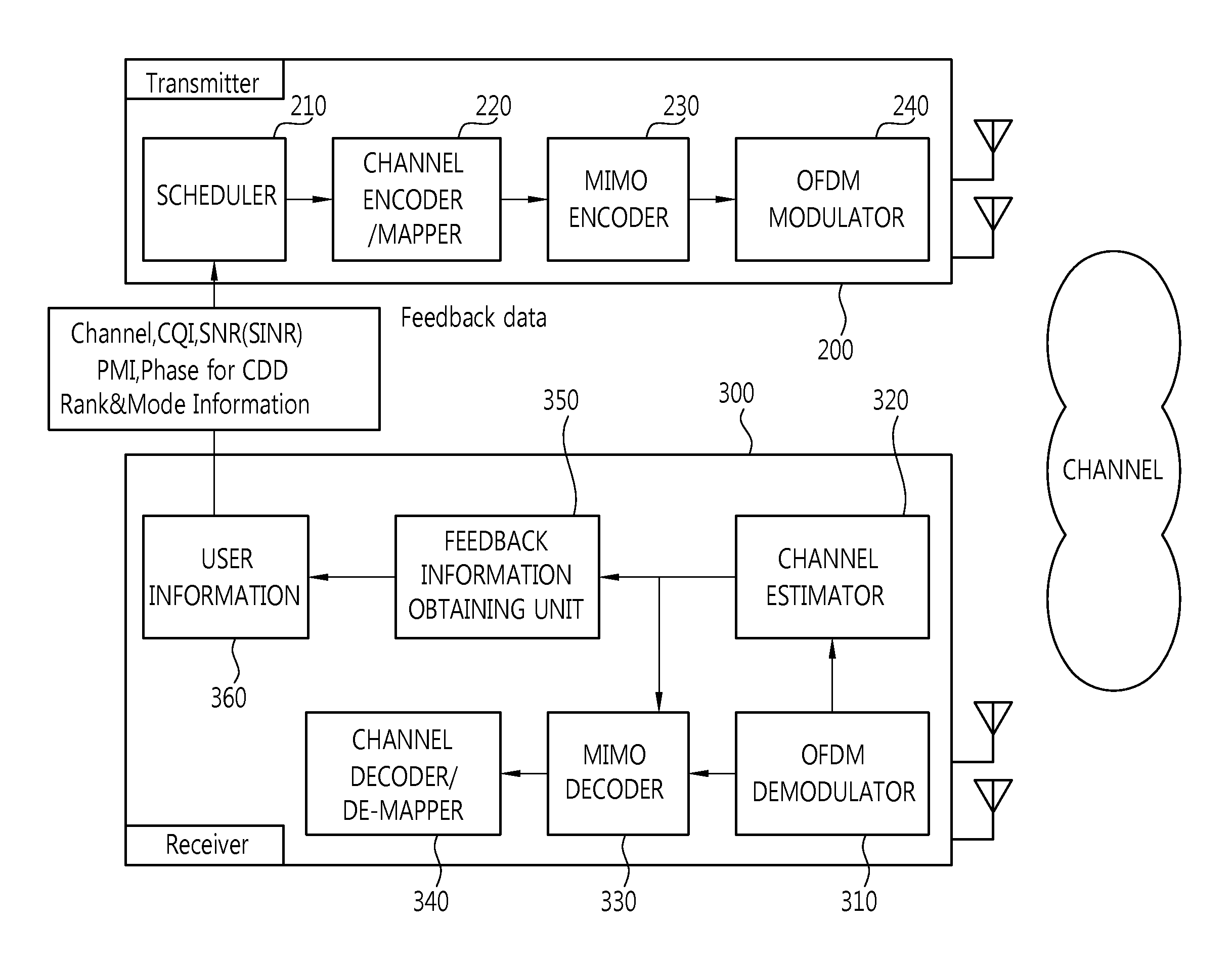
[0017]Hereinafter, a downlink (DL) denotes a communication link from the BS 20 to the UE 10, and an uplink (UL) denotes a communication link from the UE 10 to the BS 20. In the DL, a transmitter may be a part of the BS 20, and a receiv...


PUM


Abstract

A method for transmitting data in a multiple antenna system comprises the steps of: generating a transmission signal in plural antennas through the application of a precoding eight matrix to first and second antenna clusters including the plural antennas, and transmitting the transmission signal. The precoding weight matrix is a block diagonal matrix that is configured in a precoding weight corresponding to first and second antenna clusters respectively. The precoding weight of the first antenna cluster is selected according to a channel condition, and the precoding weight of the second antenna cluster is selected regardless of the channel condition but according to a rule.

Description

TECHNICAL FIELD[0001]The present invention relates to wireless communications, and more particularly, to a data transmission method using multiple antennas.BACKGROUND ART[0002]To maximize performance and communication capability of a wireless communication system, a multiple input multiple output (MIMO) system has drawn attention in recent years. Being evolved from the conventional technique in which a single transmit (Tx) antenna and a single receive (Rx) antenna are used, a MIMO technique uses multiple Tx antennas and multiple Rx antennas to improve transfer efficiency of data to be transmitted or received. The MIMO system is also referred to as a multiple antenna system. In the MIMO technique, instead of receiving one whole message through a single antenna path, data segments are received through a plurality of antennas and are then collected as one piece of data. As a result, a data transfer rate can be improved in a specific range, or a system range can be increased with respec...

Claims


Application Information

Patent Timeline
IPC IPC(8): H04W16/00
CPCH04B7/0413H04B7/0456H04B7/06
Inventor KO, HYUN SOOCHUN, JIN YOUNGLEE, MOON ILIHM, BIN CHULLEE, WOOK BONG
Owner LG ELECTRONICS INC
Why Eureka
Try Eureka