Method for doping non-planar transistors

a non-planar, doping technology, applied in the direction of basic electric elements, electrical equipment, semiconductor devices, etc., can solve the problems of poor contact, ion implantation damage the crystal structure of silicon, and inability to achieve doping techniques, etc., to achieve the effect of increasing the concentration of the doped conformal silicon glass layer

Inactive Publication Date: 2011-06-02
APPLIED MATERIALS INC
View PDF3 Cites 106 Cited by
  • Summary
  • Abstract
  • Description
  • Claims
  • Application Information

AI Technical Summary

Benefits of technology

The invention relates to methods for doping non-planar silicon features formed over a substrate. The inventors found that techniques used for doping planar structures are not ideal for non-planar structures and developed a new and improved technique. The methods involve depositing a doped conformal silicate glass layer over the raised patterned silicon features, diffusing dopant from the glass layer into the silicon features, and removing the glass layer. The methods can be used for various non-planar structures such as vertical transistors, multi-gate non-planar structures, solar cells, and deep trench structures. The invention provides a more effective and efficient way to dope non-planar silicon features.

Problems solved by technology

The patent text discusses the problem of doping non-planar structures, such as those found in semiconductor devices and solar cells, while maintaining their structural integrity. Non-planar structures have become more popular in recent years but doping them can be challenging due to their small size and lack of structural support. The technical problem is to find better techniques and methods for uniformly doping non-planar structures.

Method used


Image

  • Method for doping non-planar transistors
  • Method for doping non-planar transistors
  • Method for doping non-planar transistors

Examples


Embodiment Construction

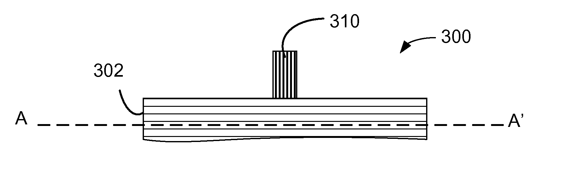
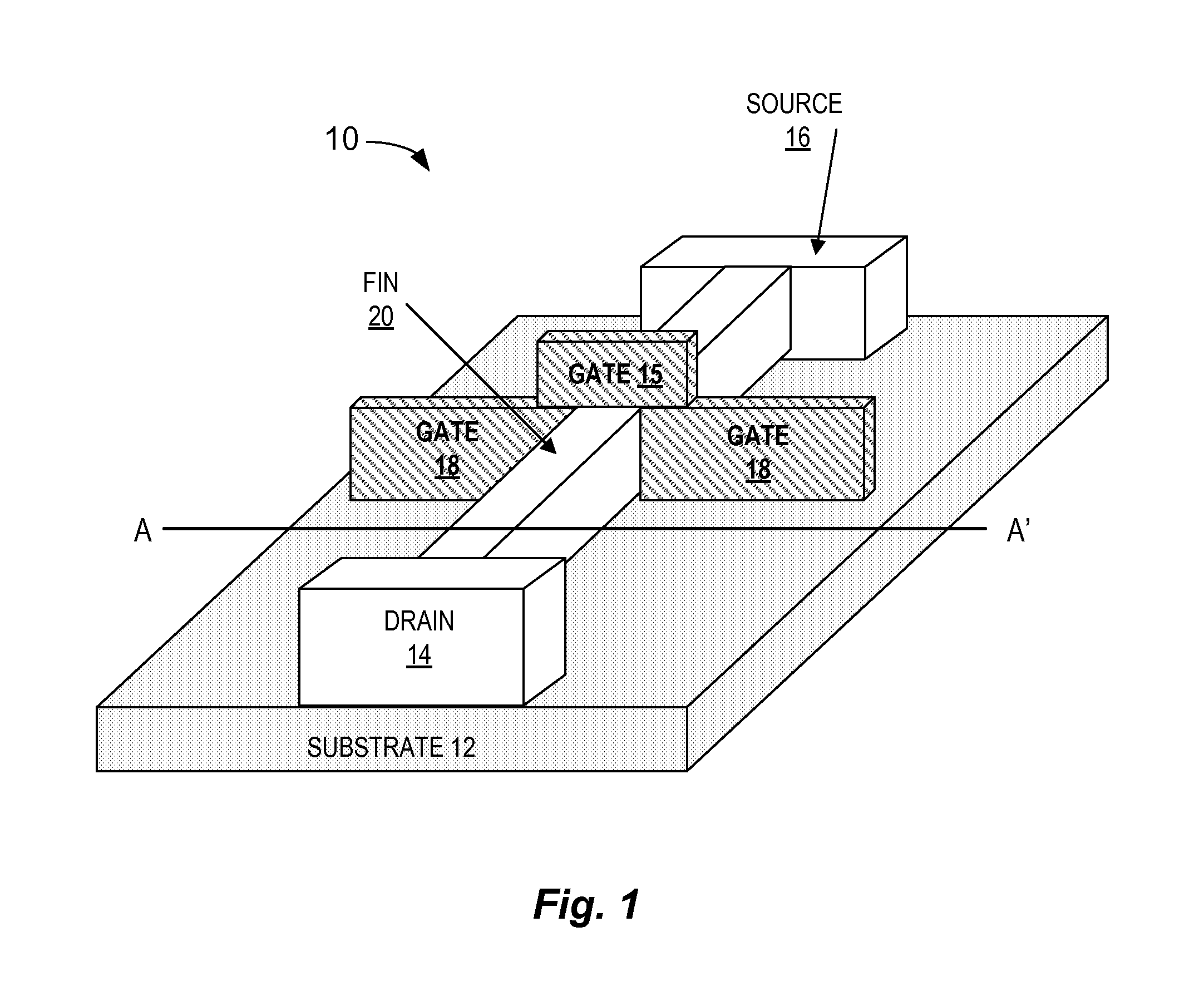
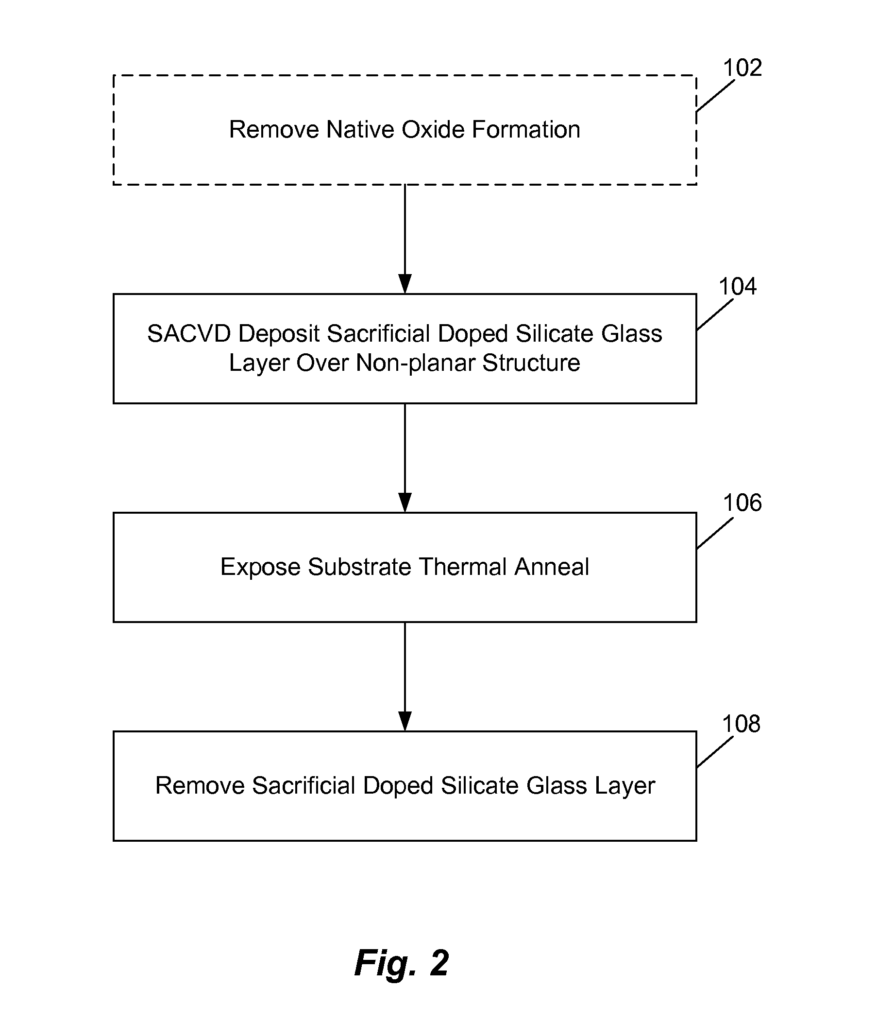
[0016]Doping non-planar structures require a degree of controllability that may be grater than what is needed for similarly dimensioned planar structures. For example, for multi-gate structures such as FINFET 10 shown in FIG. 1, uniform doping of the FIN structure helps to achieve Vt uniformity. Achieving this with ion implantation may require ion bombardment at large tilt angles that makes the process expensive and complex. The present inventors have come up with an improved dopant diffusion process that may advantageously be used to dope non-planar structures where doping uniformity and structural integrity is important. One embodiment of the method of the present invention uses a thermally driven SACVD deposition process to deposit a highly conformal sacrificial doped silicate glass layer over the non-planar structure. Deposition conditions are carefully controlled as described below to optimize dopant uniformity in a manner that is particularly well suited for non-planar structu...


PUM


Abstract

Methods for doping a non-planar structure by forming a conformal doped silicon glass layer on the non-planar structure are disclosed. A substrate having the non-planar structure formed thereon is positioned in chemical vapor deposition process chamber to deposit a conformal SACVD layer of doped glass (e.g. BSG or PSG). The substrate is then exposed to RTP or laser anneal step to diffuse the dopant into the non-planar structure and the doped glass layer is then removed by etching.

Description


Claims


Application Information

Patent Timeline
Owner APPLIED MATERIALS INC
Why Eureka
Try Eureka