
Shadow mask alignment and management system

a technology of management system and shadow mask, applied in the field of thin film batteries, can solve the problems of large overhead and yield loss of shadow masks

Inactive Publication Date: 2011-06-09
APPLIED MATERIALS INC
View PDF9 Cites 25 Cited by
  • Summary
  • Abstract
  • Description
  • Claims
  • Application Information

AI Technical Summary

Problems solved by technology

The overhead associated with shadow masks may be considerable as well as lead to yield loss in the event of misalignment.

Method used


Image

  • Shadow mask alignment and management system
  • Shadow mask alignment and management system
  • Shadow mask alignment and management system

Examples


Embodiment Construction

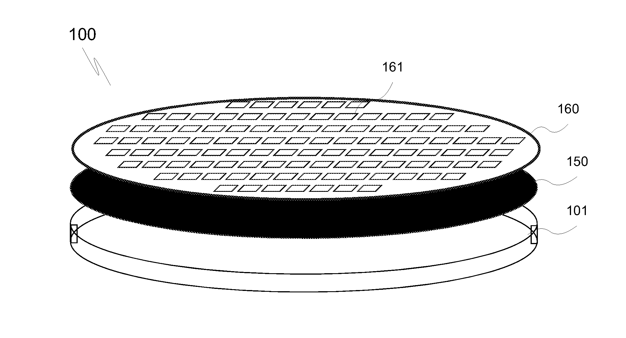
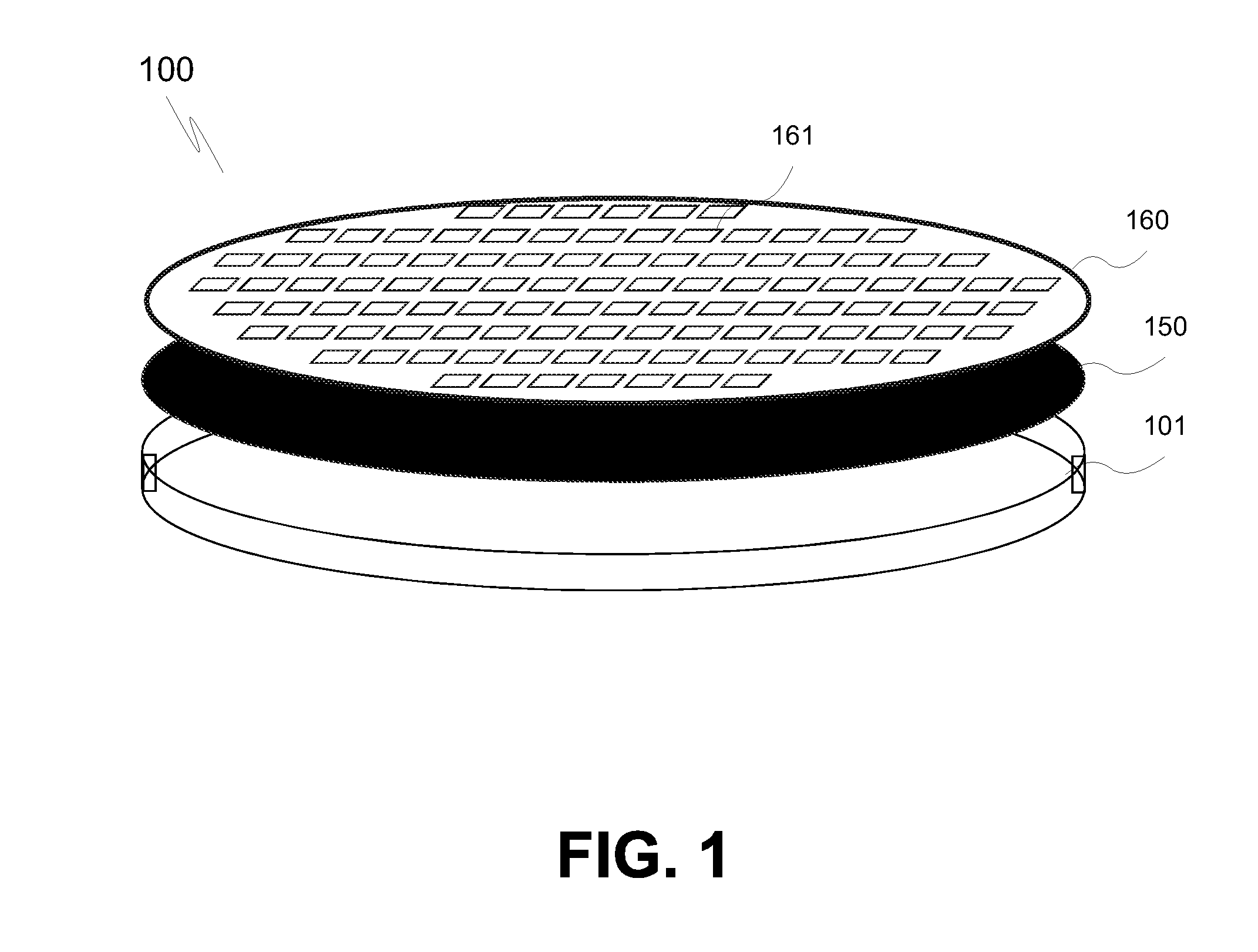
Shadow mask fixation and shadow mask alignment methods and apparatuses are described. In the following description, numerous specific details are set forth, such as component materials, component combinations, equipment platforms and processing operations in order to provide a thorough understanding of the present invention. It will be apparent to one skilled in the art that the present invention may be practiced without one or more of these specific details. In other instances, well-known features, such as pattern recognition algorithms, equipment control algorithms and the like are not described in detail in order to not unnecessarily obscure the present invention. Furthermore, it is to be understood that the various exemplary embodiments shown in the figures are illustrative representations and are not necessarily drawn to scale.

The terms “over,”“under,”“between,” and “on” as used herein refer to a relative position of one member with respect to other members. As such, for exampl...


PUM

PropertyMeasurementUnit
thicknessaaaaaaaaaa
diameteraaaaaaaaaa
diameteraaaaaaaaaa

Abstract

A magnetic handling assembly for thin-film processing of a substrate, a system and method for assembling and disassembling a shadow mask to cover a top of a workpiece for exposure to a processing condition. The assembly may include a magnetic handling carrier and a shadow mask disposed over, and magnetically coupled to, the magnetic handling carrier to cover a top of a workpiece that is to be disposed between the shadow mask and the magnetic handling carrier when exposed to a processing condition. A system includes a first chamber with a first support to hold the shadow mask, a second support to hold a handling carrier, and an alignment system to align the shadow mask a workpiece to be disposed between the carrier and shadow mask. The first and second supports are moveable relative to each other.

Description

FIELDEmbodiments of the present invention pertain to the field of thin-film batteries and, in particular, to shadow mask fixation and alignment systems and methods.DESCRIPTION OF RELATED ARTRecent efforts towards scaling the dimensions of thin-film batteries (TFB) to include ever smaller features while increasing capacities for high volume manufacturing of such thin-film batteries have mostly relied on traditional thin-film battery manufacturing methods and techniques. Such traditional methods and techniques may include the use of a shadow mask, or a set of shadow masks, at each and every deposition operation in a typical thin-film battery process flow. For example, in a conventional process, a processing tool is loaded with a shadow mask, deposition of a single layer is performed in the processing tool, and a first shadow mask is then unloaded for replacement with a second shadow mask intended for another deposition operation.The overhead associated with shadow masks may be conside...

Claims


Application Information

Patent Timeline
Patent Type & Authority Applications(United States)
IPC IPC(8): H05K13/04
CPCH01M4/02H01M4/13H01M4/139H01M4/5825H01M4/621Y10T29/5313H01M4/663H01M2004/028Y02E60/122C23C14/042Y10T29/49002H01M4/623Y02E60/10Y02P70/50H01M6/40H01M10/0404
Inventor KWAK, BYUNG-SUNG LEOBANGERT, STEFANHOFMANN, RALFKOENIG, MICHAEL
Owner APPLIED MATERIALS INC
Features
  • Generate Ideas
  • Intellectual Property
  • Life Sciences
  • Materials
  • Tech Scout
  • Unparalleled Data Quality
  • Higher Quality Content
  • 60% Fewer Hallucinations
Learn More