Flowmeter and method

Active Publication Date: 2011-06-09
CAMERSON INT CORP
View PDF8 Cites 16 Cited by
  • Summary
  • Abstract
  • Description
  • Claims
  • Application Information

AI Technical Summary

Benefits of technology

[0005]The present invention is applicable for measuring flow rates, particularly low flow rates, with ultrasonic transit time technology. The application is specifically applied to monitoring chemical fluid injection in subsea oil wells. The invention

Problems solved by technology

The noise level is significant because it reduces the accuracy of the fl

Method used


Image

  • Flowmeter and method
  • Flowmeter and method
  • Flowmeter and method

Examples


Embodiment Construction

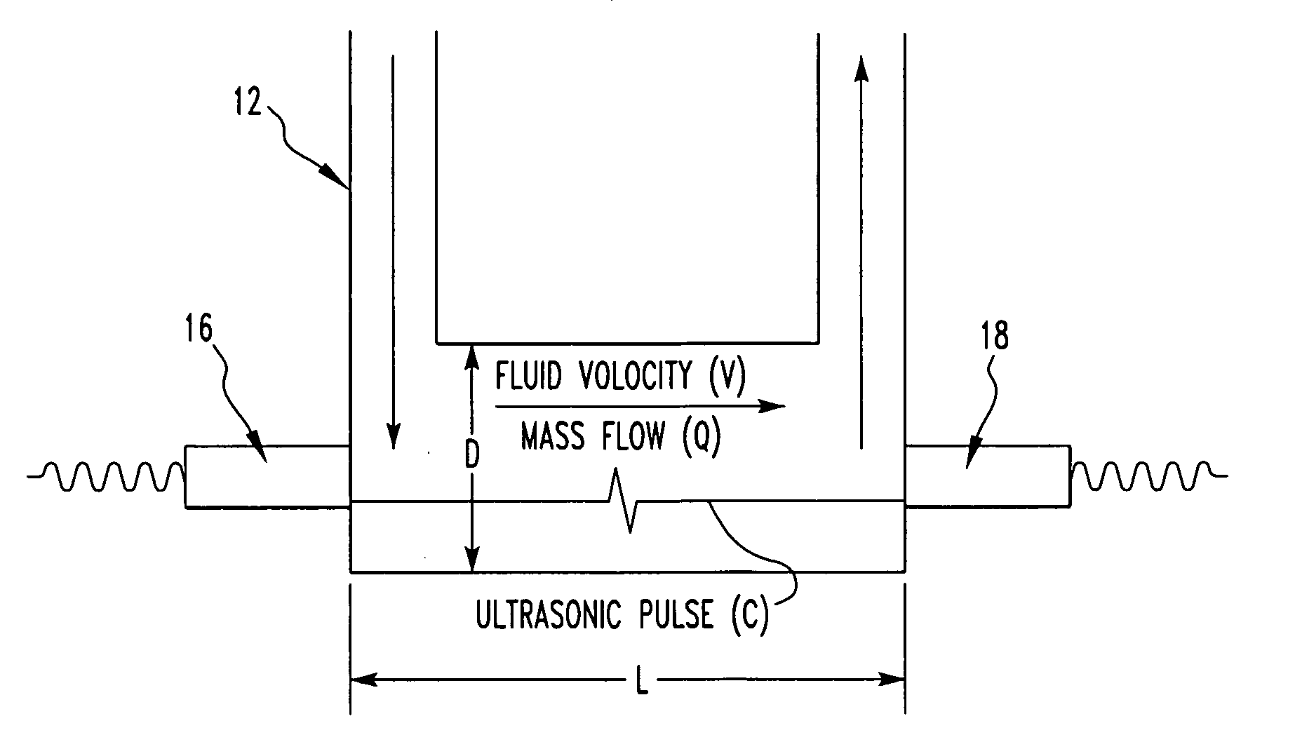
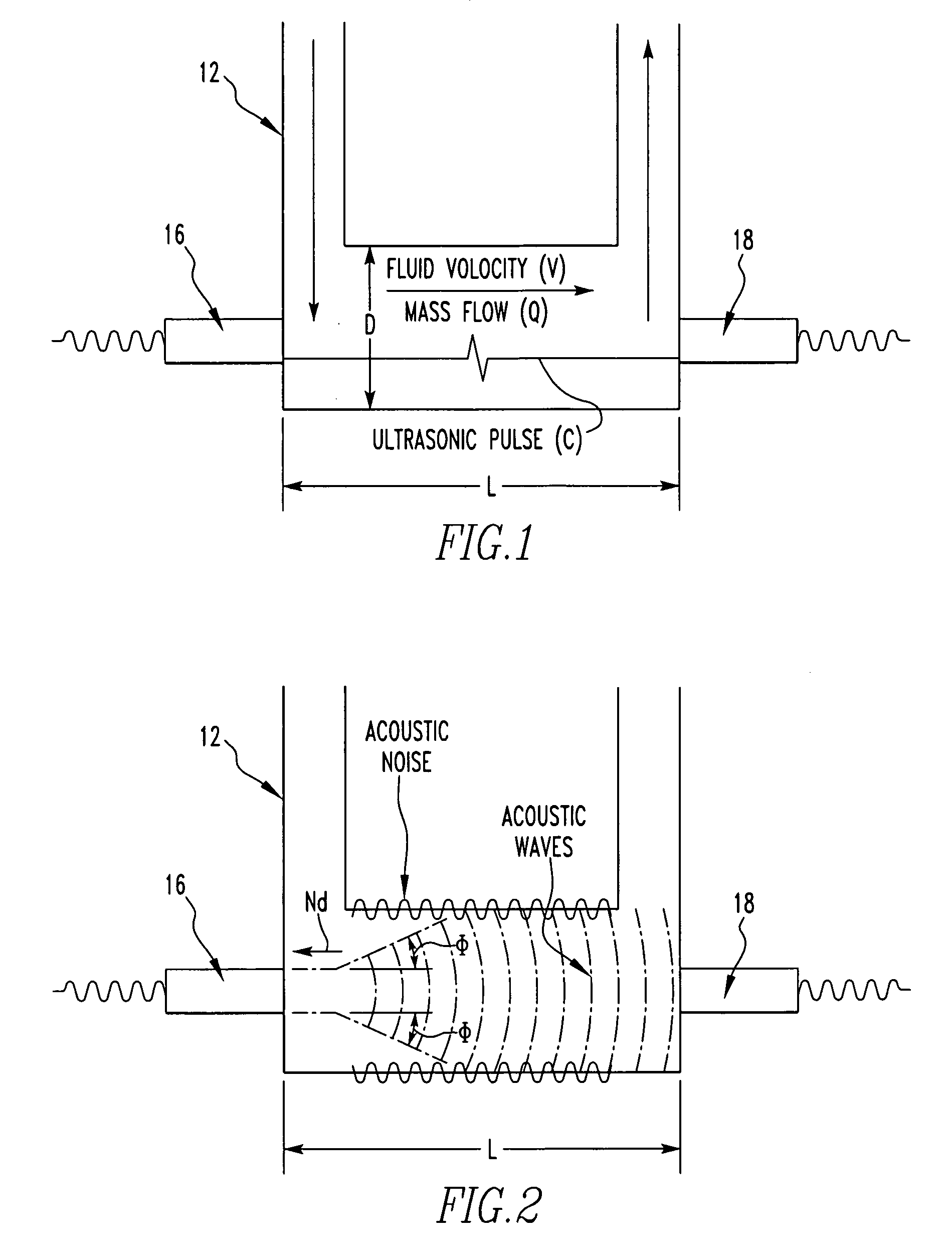
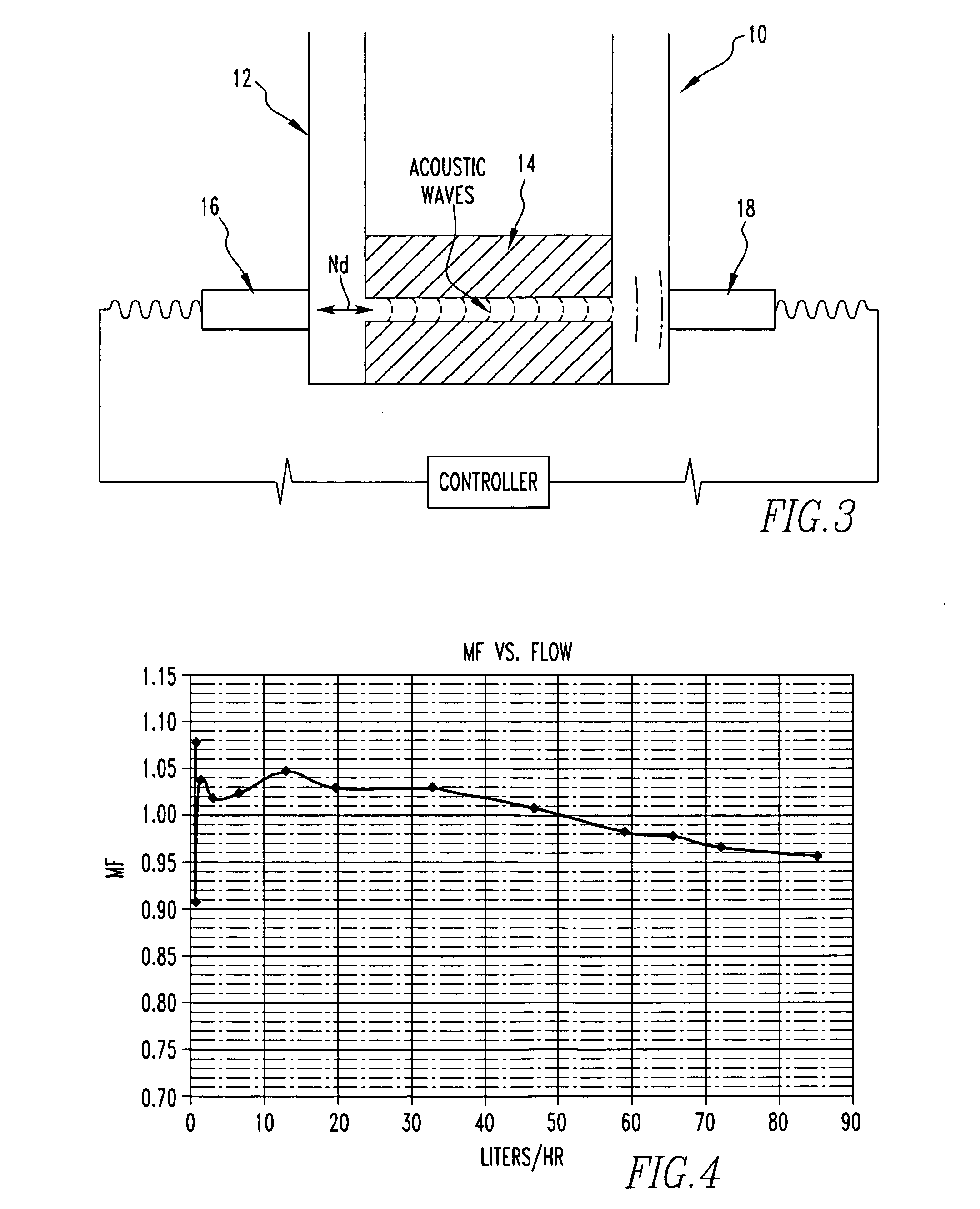
[0011]Referring now to the drawings wherein like reference numerals refer to similar or identical parts throughout the several views, and more specifically to FIGS. 1 and 3 thereof, there is shown a flowmeter 10 for detecting fluid flow rates in a pipe 12. The flowmeter 10 comprises a tube 14 having a channel disposed in the pipe 12 through which fluid in the pipe 12 flows. The flowmeter 10 comprises an upstream ultrasonic transducer in contact with the pipe 12 and positioned in alignment with the channel so plane waves generated by the upstream transducer 16 propagate through the channel. The flowmeter 10 comprises a downstream ultrasonic transducer in contact with the pipe 12 and positioned so plane waves generated by the downstream transducer 18 propagate through the channel and are received by the upstream transducer 16 which produces an upstream transducer 16 signal. The downstream transducer 18 receives the plane waves from the upstream transducer 16 and provides a downstream ...


PUM

PropertyMeasurementUnit
Flow rateaaaaaaaaaa
Sizeaaaaaaaaaa
Wavelengthaaaaaaaaaa

Abstract

A flowmeter for detecting fluid flow rates in a pipe includes a tube having a channel disposed in the pipe through which fluid in the pipe flows. The flowmeter includes an upstream transducer in contact with the pipe and positioned so plane waves generated by the upstream transducer propagates through the channel. The flowmeter includes a downstream transducer in contact with the pipe and positioned so plane waves generated by the downstream transducer propagate through the channel and are received by the upstream transducer which produces an upstream transducer signal. The downstream transducer receives the plane waves from the upstream transducer and provides a downstream transducer signal. The flowmeter includes a controller in communication with the upstream and downstream transducers which calculate fluid flow rate from the upstream transducer signal and the downstream transducer signal. A method for detecting fluid flow rates in a pipe.

Description

FIELD OF THE INVENTION[0001]The present invention is related to a flowmeter for detecting fluid flow rates in a pipe having a tube with a channel disposed in the pipe through which fluid in the pipe flows and plane waves generated by an upstream ultrasonic transducer and a downstream ultrasonic transducer propagate. (As used herein, references to the “present invention” or “invention” relate to exemplary embodiments and not necessarily to every embodiment encompassed by the appended claims.) More specifically, the present invention is related to a flowmeter for detecting fluid flow rates in a pipe having a tube with a channel disposed in the pipe through which fluid in the pipe flows and plane waves generated by an upstream ultrasonic transducer and a downstream ultrasonic transducer propagate, where the tube is made of a sound absorbing material so that essentially all non-fluid paths of sound are absorbed.BACKGROUND OF THE INVENTION[0002]This section is intended to introduce the r...

Claims


Application Information

Patent Timeline
IPC IPC(8): G01F1/66
CPCG01F1/662G01F1/667Y10T29/494Y10T29/49826G01F1/66G01P5/24
Inventor GOTTLIEB, EMANUELAUGENSTEIN, DONALD R.
Owner CAMERSON INT CORP
Why Eureka
Try Eureka