Back Flow Prevention System

a backflow and prevention system technology, applied in the direction of service pipe systems, functional valve types, valve operating means/releasing devices, etc., can solve problems such as flooding buildings, and achieve the effects of low cost, reliable cleaning, and convenient cleaning

Inactive Publication Date: 2011-06-09
UTAH STATE UNIVERSITY
View PDF3 Cites 26 Cited by
  • Summary
  • Abstract
  • Description
  • Claims
  • Application Information

AI Technical Summary

Benefits of technology

[0007]The system comprises two rubber flaps attached in such a way that fluid is allowed to flow through a channel between the two flaps in only one direction. The pressure of the fluid on the flaps during a backflow causes the channel to seal itself against the fluid flow. The system also employs a warning alarm to alert the user of a backflow problem. The two flaps, which lie in the valve housing, are attached to each other on the sides. The flaps may be two individual pieces of rubber or may be a single piece of rubber. The flaps are attached to an inlet pipe coming from the building in a way to keep the flaps in an open position to allow water to flow through the valve. The open position allows fluid to flow through the valve if the fluid is flowing away from the building. The edges of the flaps that run parallel with the pipes are attached to each other. At least one anchor is used to attach the flaps to the valve housing or another internal structural component in the corners of the flaps at the exit of the valve. The two flaps lie on the bottom of the valve housing, with one flap on top of the other, both flaps following the curvature of the valve housing. The flaps lie on top of one another in such a way to make a seal when fluid flows back toward the outlet pipe of the building instead of flowing away from it. The bottom flap may be attached to the bottom of the inside of the valve housing so as to prevent the bottom flap from moving and preventing the valve from folding in on itself. The sides of the flaps are sealed together to prevent the flow of fluid in or out of the channel on the sides. An alarm sensor is mounted within the valve housing but outside the one-way rubber valve. When fluid begins to flow back toward the one-way valve and inlet pipe, the fluid accumulates outside the channel, because it cannot flow back through the valve. As the fluid level rises in the valve housing, it is detected by the sensor which communicates with an alarm to notify the user of a backflow issue. This provides an early warning notification of a backflow problem. This one-way valve creates a leak-proof seal. The valve is easily cleaned and no power is needed. It provides a reliable, low-cost solution to an increasing problem. When cleaning is needed the valve can be cleaned without folding inside out. It also provides an early warning notification for users.

Problems solved by technology

When sewer and other fluid systems experience heavy flow or obstructions, the fluid can be backed up, creating strong reverse pressure to residential and business plumbing systems, resulting in flooding buildings.

Method used


Image

  • Back Flow Prevention System
  • Back Flow Prevention System
  • Back Flow Prevention System

Examples


Embodiment Construction

[0016]In the following description, numerous specific details are provided for a thorough understanding of specific preferred embodiments. However, those skilled in the art will recognize that embodiments can be practiced without one or more of the specific details, or with other methods, components, materials, etc. In some cases, well-known structures, materials, or operations are not shown or described in detail in order to avoid obscuring aspects of the preferred embodiments. Furthermore, the described features, structures, or characteristics may be combined in any suitable manner in a variety of alternative embodiments. Thus, the following more detailed description of the embodiments of the present invention, as represented in the drawings, is not intended to limit the scope of the invention, but is merely representative of the various embodiments of the invention.

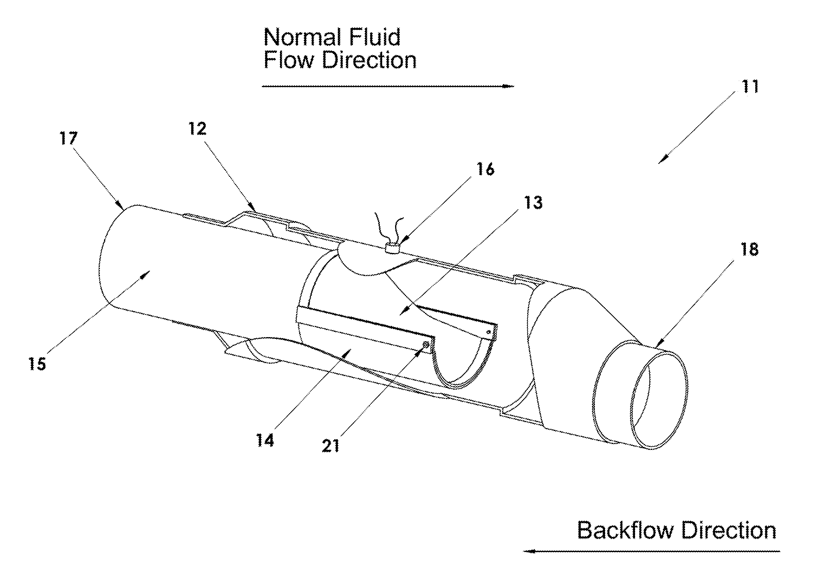
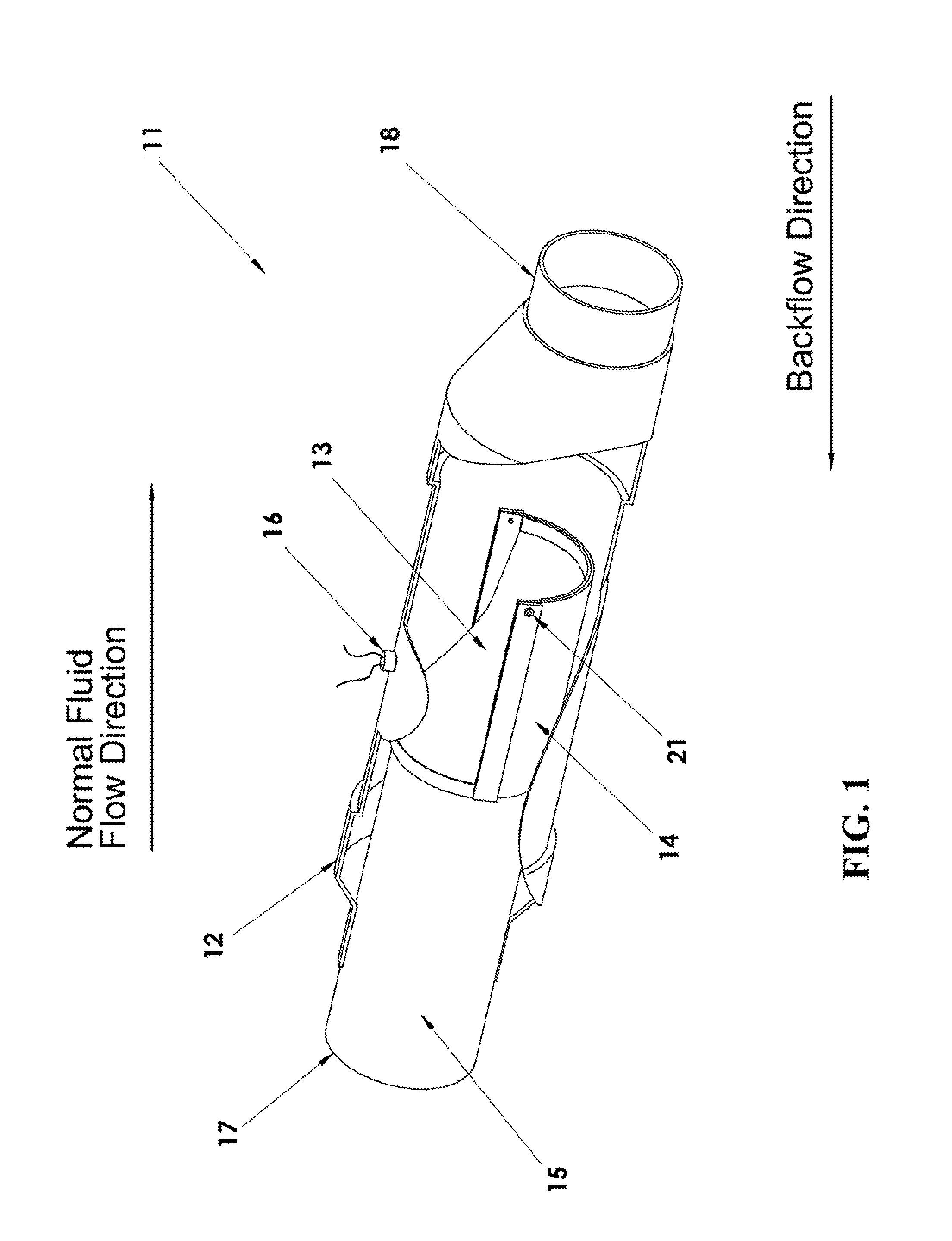
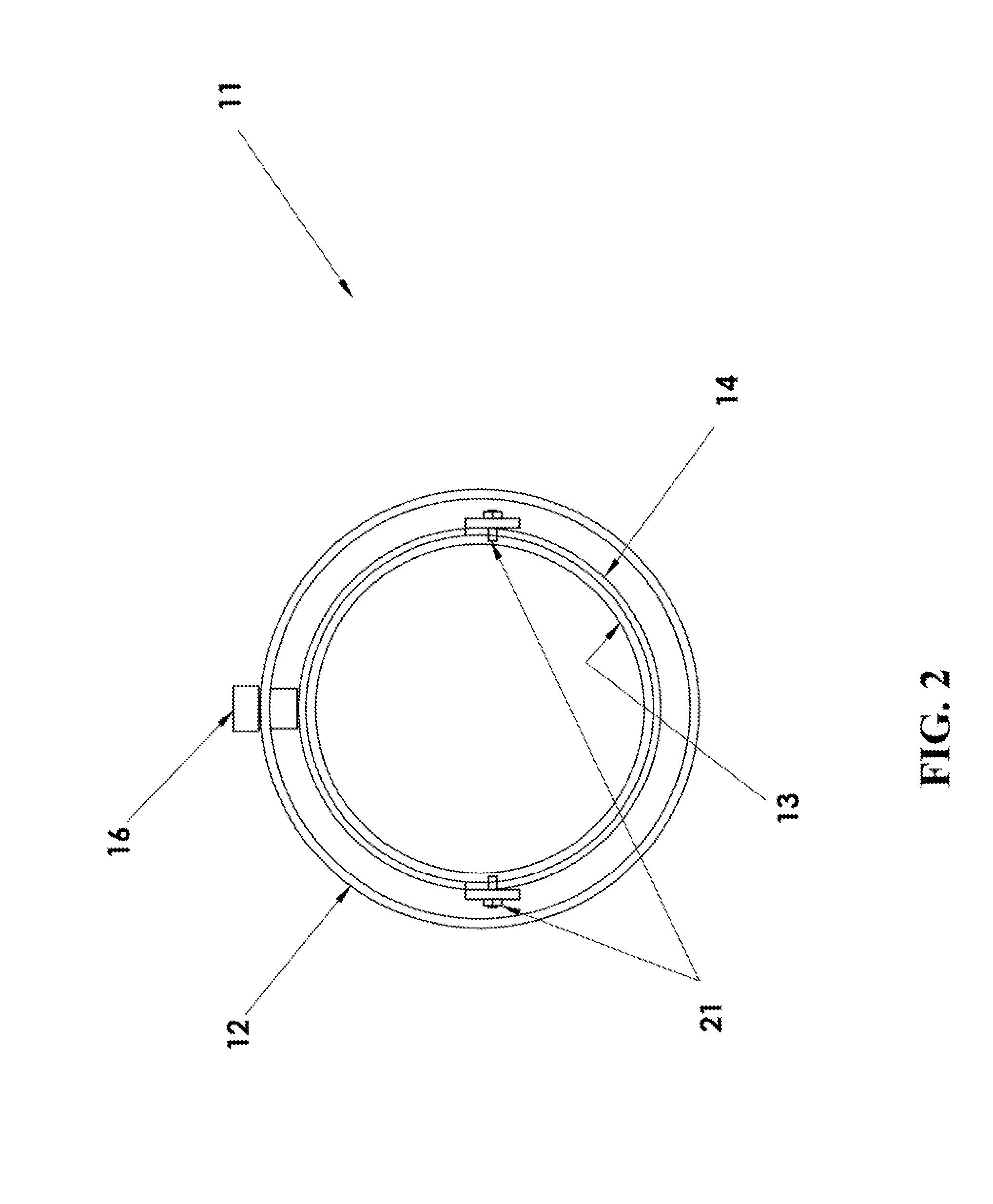
[0017]Backflow of waste water has caused serious damage for home and business owners when their basements flood. The...


PUM


Abstract

A system that prevents the backflow of fluid is disclosed. The system comprises a housing, two rubber flaps that are attached in such a way to create a one-way valve, and a water sensor. The flaps are anchored to the inside of the housing and open due to the force of fluid flowing in one direction. Fluid flowing in the opposite direction presses the ends of the flaps against each other, thus closing the valve and preventing water from backflowing through the system. A water sensor, mounted within the housing, is activated when a backflow fills the housing, thus providing an alarm to indicate a backflow event has occurred.

Description

FIELD OF THE INVENTION[0001]This invention relates to a backflow prevention system and in particular to a one-way valve that utilizes flexible rubber flaps to prevent fluid flow in an undesired direction.BACKGROUND OF THE INVENTION[0002]Sewer systems containing pipes provide a way to remove dirty water and waste from residential dwellings and businesses. During rain storms and other times of high liquid volumes or when obstructions are introduced, the sewer systems can become backed up, and the waste water flows back through the pipes into homes and businesses causing serious and costly damage. Each year in the United States sewers back up in basements several hundred thousand times from the more than 50,000 municipal sanitary systems that overflow. Harmful pathogens are released and conditions are created where black mold can grow. Often the backflow problems arise when raw sewage and storm drainage use the same pipeline. During heavy rainfall, system may become overloaded causing ...

Claims


Application Information

Patent Timeline
Patent Type & Authority Applications(United States)
IPC IPC(8): F16K31/12F16K37/00
CPCE03F7/04F16K37/005F16K15/147E03F2201/20Y10T137/7761Y10T137/8158
Inventor REESE, JAMES T.WHITE, RONALD
Owner UTAH STATE UNIVERSITY
Why Eureka
Try Eureka