Touch display panel and touch substrate

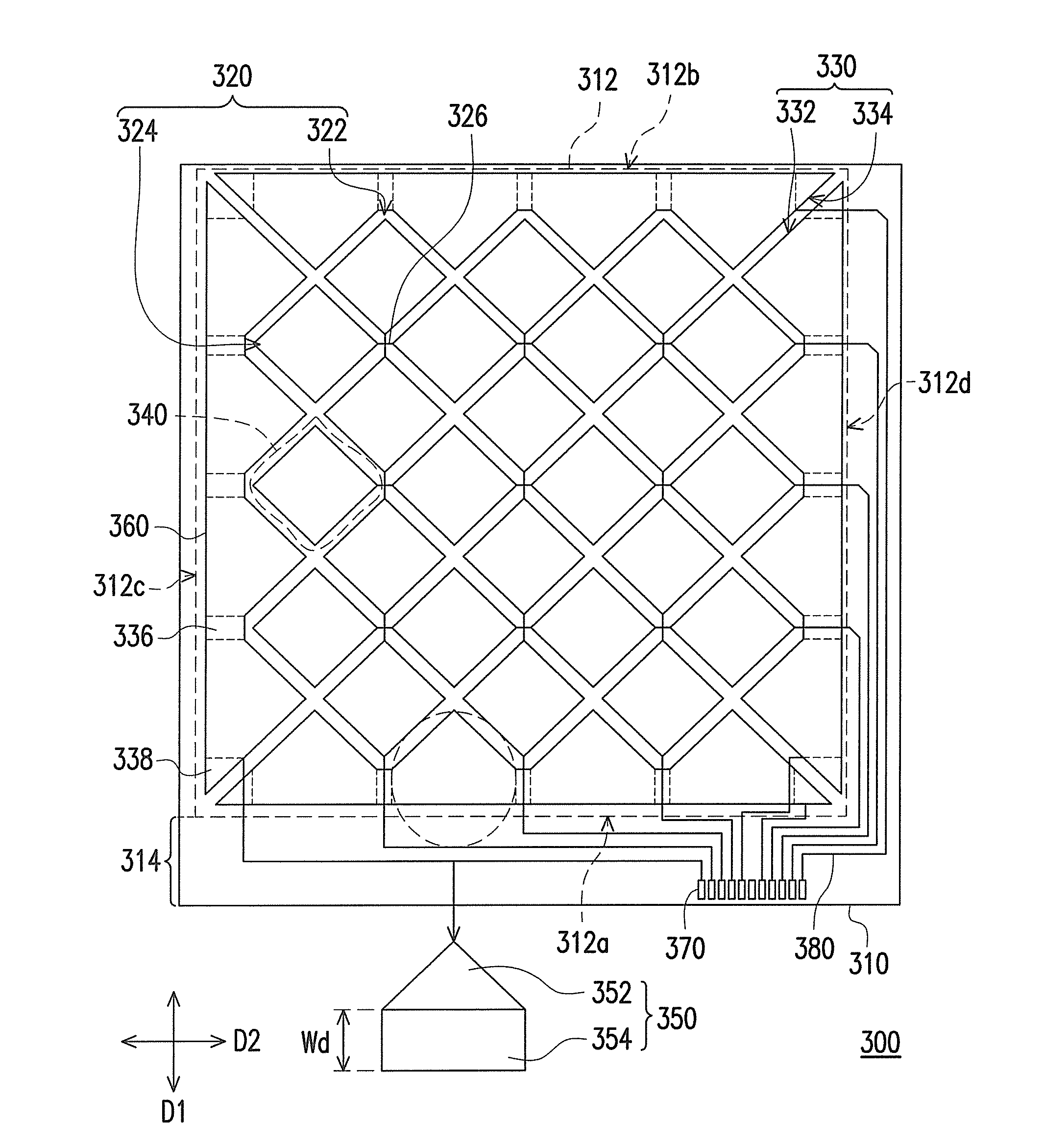
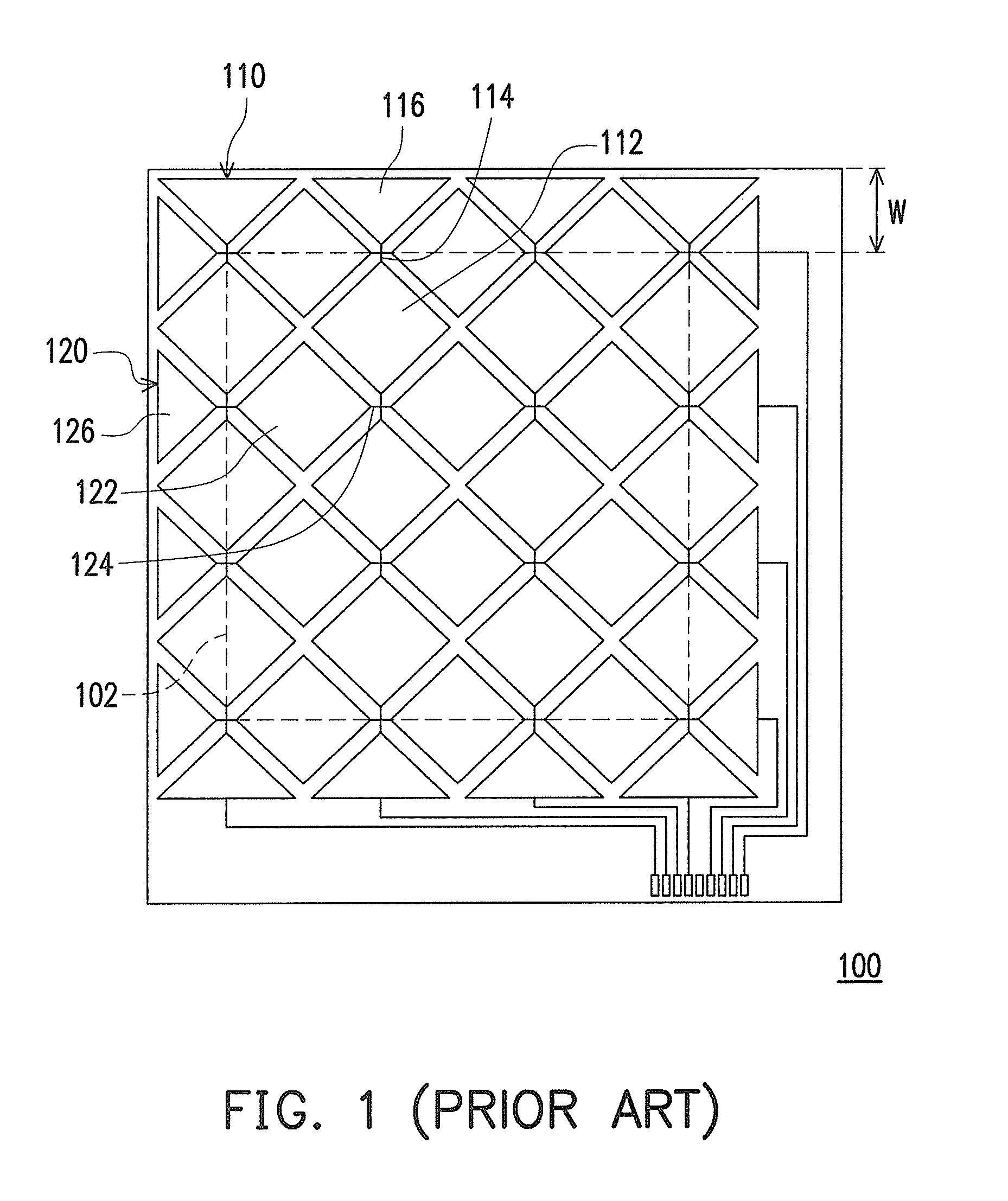
a touch display panel and substrate technology, applied in the field can solve the problem that the active area 102 is incapable of being expanded, and achieve the effect of convenient touch display panels, efficient increase of area utilization of touch display panels and touch sensing substrates

Active Publication Date: 2011-06-09
AU OPTRONICS CORP
View PDF3 Cites 52 Cited by
  • Summary
  • Abstract
  • Description
  • Claims
  • Application Information

AI Technical Summary

Benefits of technology

[0025]In view of the above, the touch display panel and the touch sensing substrate of the invention have at least a margin sensing series respectively. The margin sensing series forms a parallel hemline capable of parallel to the margin of the display area. Therefore, all the sensing series can be disposed inside the display area, which facilitates the touch display panel and the touch sensing substrate to have slim border. Namely, no dummy margin area which is incapable of sensing for disposing the protruding portion of the sensing electrodes in the touch display panel and the touch sensing substrate is required such that the area utilizations of the touch display panel and the touch sensing substrate are efficiently increased.

Problems solved by technology

However, the areas of the first margin electrodes 116 and the second margin electrodes 126 are too small to be used for touch sensing such that the active area 102 is incapable of being enlarged.

Method used


Image

  • Touch display panel and touch substrate
  • Touch display panel and touch substrate
  • Touch display panel and touch substrate

Examples


Embodiment Construction

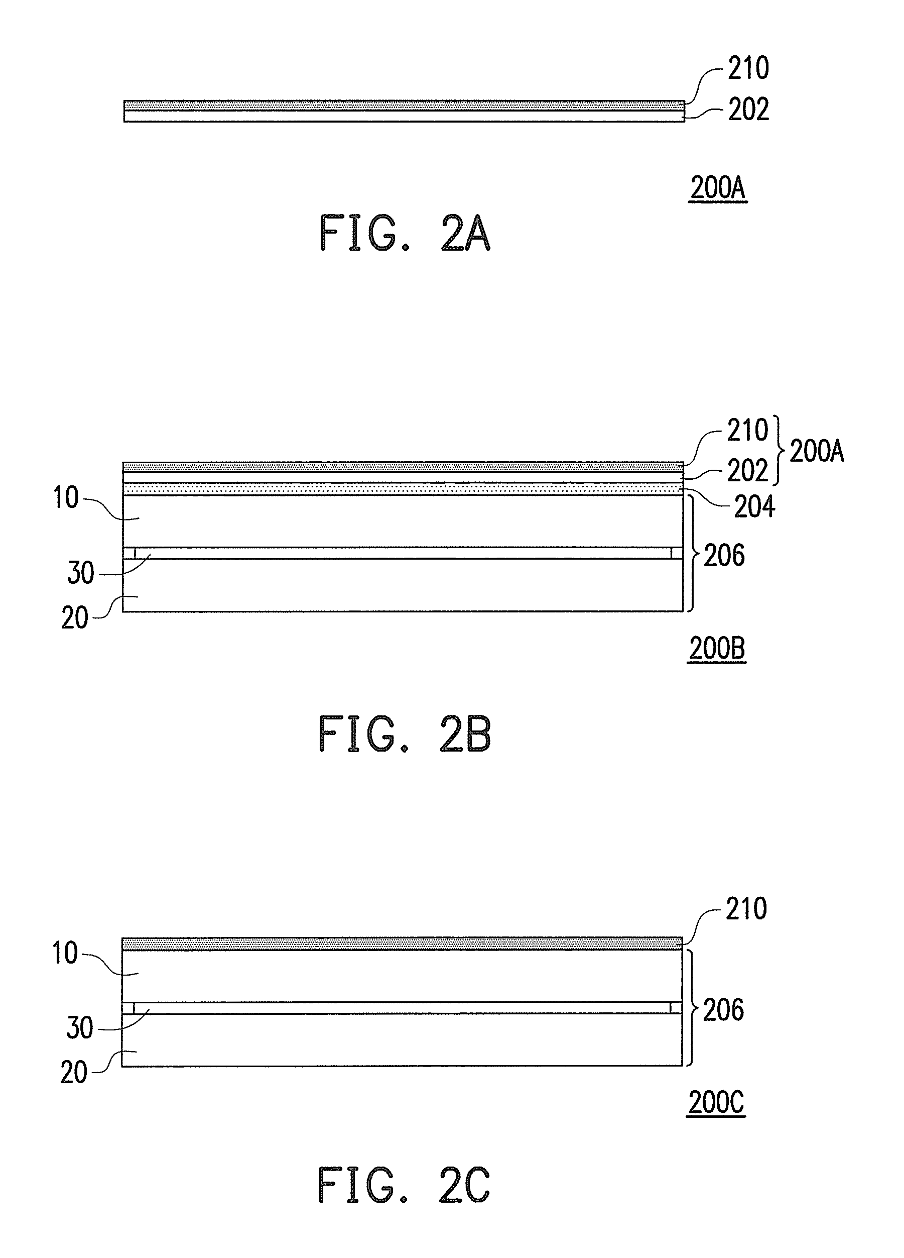
[0036]FIGS. 2A through 2C illustrate respectively a touch sensing substrate and two touch display panels according to an embodiment of the invention. Referring to FIG. 2A, the touch sensing substrate 200A includes an auxiliary substrate 202 and a touch sensing device 210 disposed on the auxiliary substrate 202. A touch display panel 200B in FIG. 2B is formed by adhering the touch sensing substrate 200A onto a flat display panel 206 through an adhesive layer 204. The flat display panel 206 is consisted of a first substrate 10, a second substrate 20, and a display media 30 sandwiched between the first substrate 10 and the second substrate 20, for example. Specifically, the flat display panel 206 can be a liquid crystal display panel, a plasma display panel, an organic electro-luminescent display panel, or an electrophoretic display panel. In addition, a touch display panel 200C is formed by directly disposing the touch sensing device 210 in the flat display panel 206 without the adhes...


PUM


Abstract

A touch display panel including a flat display panel and a touch sensing device disposed on the flat display panel is provided. The touch sensing device includes a plurality of the center sensing series and at least a margin sensing series corresponding to the display area of the flat display panel. Each center sensing series is formed by a plurality of center sensing electrodes serially connected. The margin sensing series disposed along the margin of the display area is formed by a plurality of margin sensing electrodes serially connected. Each of the margin sensing electrodes includes an inner portion and a rectangular outer portion. An area of the inner portion is substantially half of an area of the center sensing electrode. A parallel hemline is formed by the rectangular outer portions serially connected.

Description

CROSS-REFERENCE TO RELATED APPLICATION[0001]This application claims the priority benefit of Taiwan application serial no. 98142140 filed Dec. 9, 2009. The entirety of the above-mentioned patent application is hereby incorporated by reference herein and made a part of specification.BACKGROUND OF THE INVENTION[0002]1. Field of the Invention[0003]The present invention relates to a touch display panel and a touch sensing substrate, and more particularly to a touch display panel and a touch sensing substrate require merely slim boarder.[0004]2. Description of Related Art[0005]Recently, all types of electronic products are developed toward easy operation, small volume, and large screen and the demands of the volume and the screen size in the portable products are particularly stringent. Therefore, many electronic products combine a touch sensing design into a liquid crystal display panel so as to omit the space for disposing the keyboard or the operation button and enlarge the disposition...

Claims


Application Information

Patent Timeline
Patent Type & Authority Applications(United States)
IPC IPC(8): G06F3/041
CPCG06F3/044G06F3/0446
Inventor TSAI, CHANG-HSIAOHO, CHIH-HSIANG
Owner AU OPTRONICS CORP
Why Eureka
Try Eureka