Optical position detection device and projection display device

a technology of optical position detection and projection display, which is applied in the direction of measurement devices, instruments, computing, etc., can solve the problems of not being able to accurately obtain the position of the detection target object, the position detection light beam other than the position detection light beam reflected by the detection target object cannot be eliminated, and the position detection light beam cannot be easily applied. , to achieve the effect of easy light blocking, convenient operation and convenient disposal

Inactive Publication Date: 2011-06-09
SEIKO EPSON CORP
View PDF11 Cites 12 Cited by
  • Summary
  • Abstract
  • Description
  • Claims
  • Application Information

AI Technical Summary

Benefits of technology

[0021]A projection display device according to another aspect of the invention includes either one of the optical position detection devices described above, a screen provided with the reference surface, and an image projection device adapted to project an image to the screen. In this case, it is preferable that the reference surface is disposed in the range limited on the side of the light detector from an outer edge position of the projection range of the image on the side opposite to the light detector. As described above, since the reference surface is disposed so as to be limited to the side of the light detector from the outer edge position of the projection range of an image on the opposite side to the light detector, the range from which the position detection light beam is emitted is limited to the side of the light detector. Therefore, it becomes possible to easily perform the light blocking to the position detection light beam

Problems solved by technology

However, according to the optical position detection device described above, since the position detection light other than the position detection light reflected by the intended detection target object such as a fingertip or a tip of a stylus as a pointing region enters the light detector, the position of the detection target object might not be obtained accurately in some cases.
For example, since it is not achievable to accurately detect the intensity of the position detection light beam reflected by the detection target object due to the position detection light beam emitted from the display screen and then directly entering the light detector, it becomes unachievable to accurately obtain the position of the detection target object.
Further, unlike other environmental light such as outside light, the position detection light be

Method used


Image

  • Optical position detection device and projection display device
  • Optical position detection device and projection display device
  • Optical position detection device and projection display device

Examples


Embodiment Construction

[0042]Then, some embodiments of the invention will be explained in detail with reference to the accompanying drawings. It should be noted that although in the embodiments described below, an optical position detection device is applied to a projection display device, the invention is applied not only to the projection display device, but also to various types of display devices, various types of operation devices, and so on.

Overall Configuration of Projection Display Device

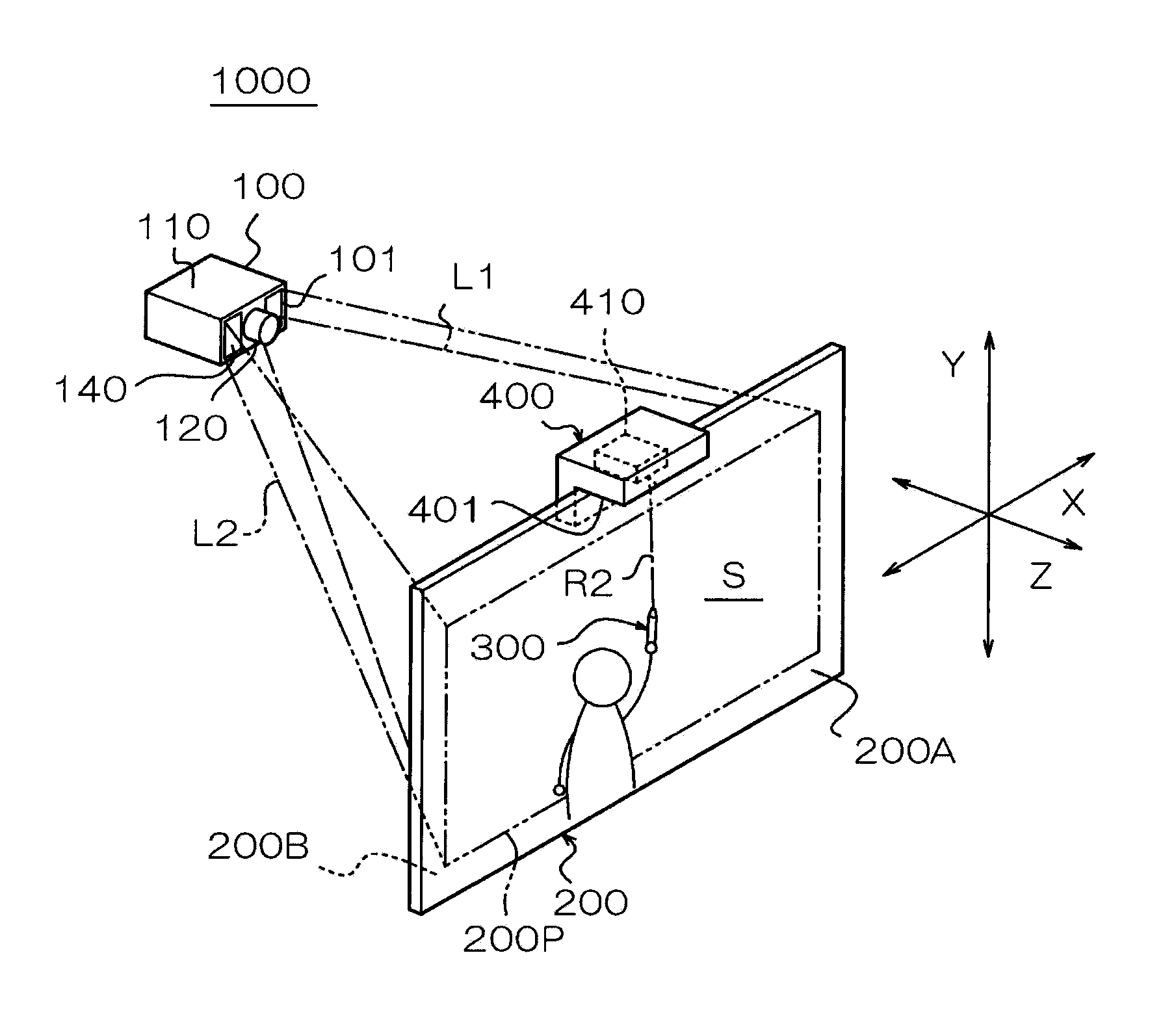
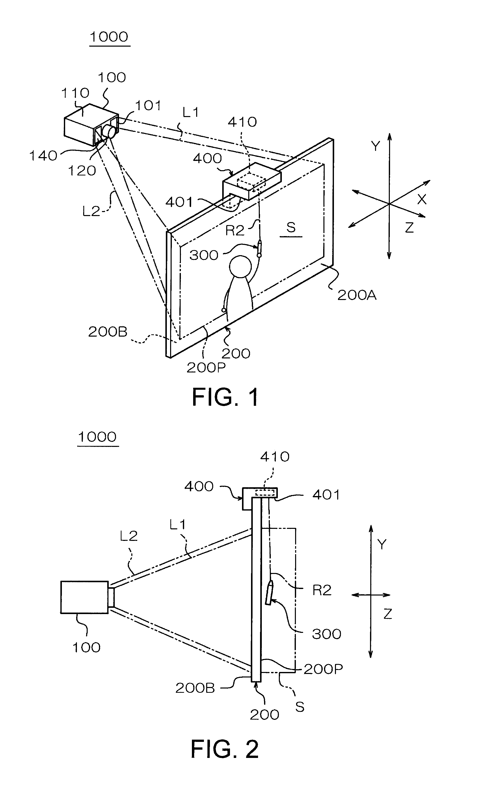
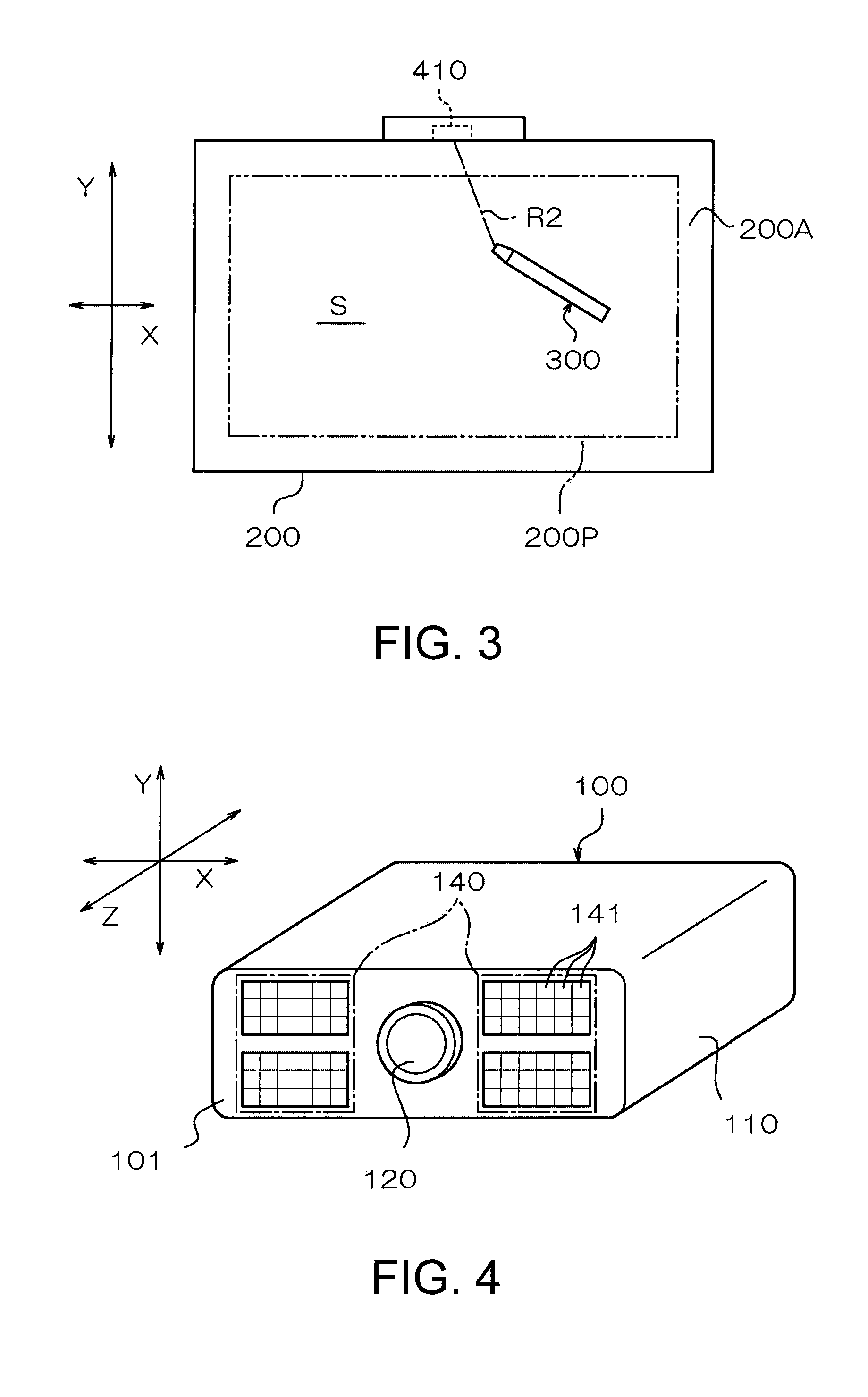
[0043]FIG. 1 is a schematic perspective view schematically showing an appearance of the projection display device according to the present embodiment of the invention viewed from a viewer side, FIG. 2 is a schematic side view schematically showing an appearance of the projection display device according to the present embodiment viewed from a lateral side, and FIG. 3 is a schematic front view schematically showing an appearance of the projection display device according to the present embodiment viewed from a view...


PUM


Abstract

An optical position detection device includes: a light source section adapted to emit a position detection light beam to form a light intensity distribution in which the intensity varies along a reference surface; a light detection section adapted to detect the position detection light reflected by a detection target object located in a detection space in which the light intensity distribution is formed; and a position detection section adapted to detect a position of the detection target object based on a detection value of the light detection section, wherein the light detection section has a light receiving section provided with a light detection surface, and a light blocking section adapted to block a part of the position detection light, and the light blocking section has an opening section disposed between the detection space and the light detection surface with a distance from the light detection surface.

Description

BACKGROUND[0001]1. Technical Field[0002]The present invention relates to an optical position detection device and a projection display device.[0003]2. Related Art[0004]In general, in various types of display devices, those provided with a touch panel function, which makes it possible to perform input instructions by touching the display screen with fingers, styluses, or the like, have been increasing. Such a touch panel function can be implemented by disposing a touch panel on a display screen.[0005]Such a touch panel function as described above can also be realized by an optical position detection device for obtaining the position of a detection target object by detecting the light (see, e.g., the specifications of U.S. Pat. Nos. 5,666,037 and 6,927,384). In such an optical position detection device, it is arranged that the position detection light beam is emitted from a light emitting element, then the position detection light beam reflected by the detection target object on a dis...

Claims


Application Information

Patent Timeline
IPC IPC(8): G06F3/042G01B11/14
CPCG06F3/0428
Inventor KIYOSE, KANECHIKA
Owner SEIKO EPSON CORP
Why Eureka
Try Eureka