

Absorbent article
- Summary
- Abstract
- Description
- Claims
- Application Information
AI Technical Summary
Benefits of technology
Problems solved by technology
Method used
Image

Examples
first embodiment
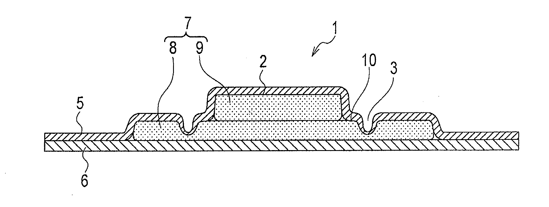
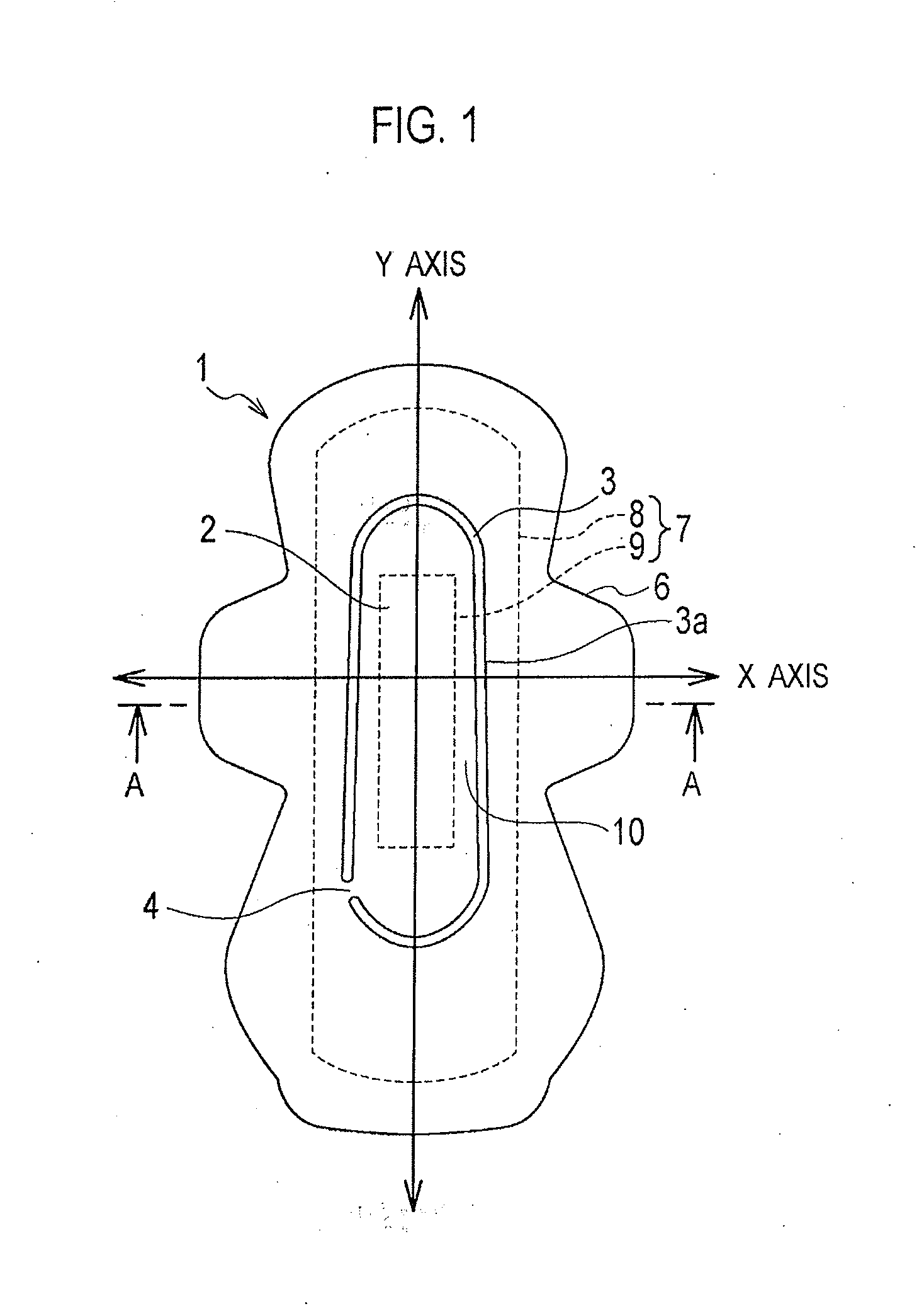
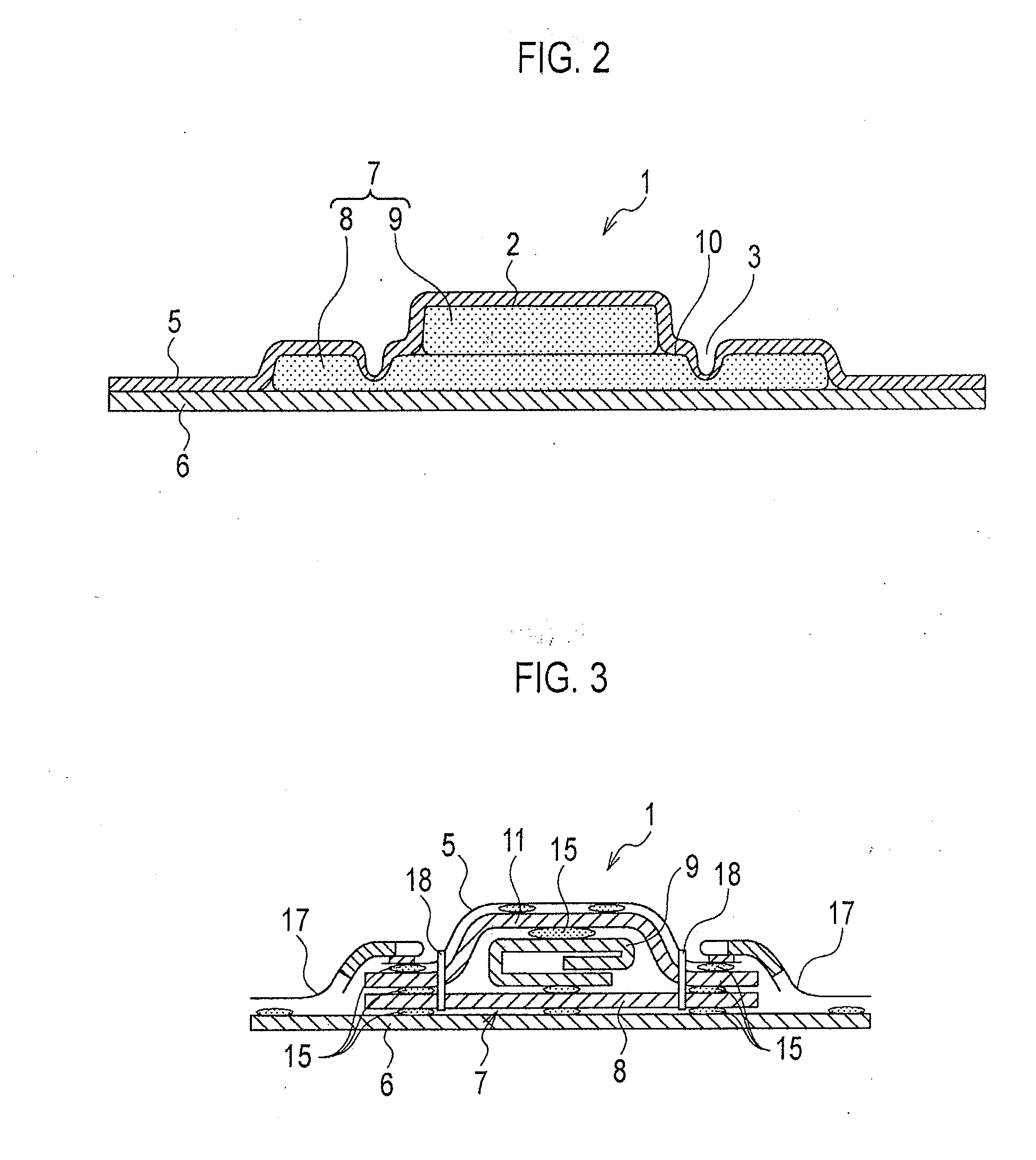
[0025]FIGS. 1 to 3 shows the present invention. FIG. 1 is a plan view. FIG. 2 is a cross-sectional view taken along the A-A line in FIG. 1. FIG. 3 is a cross-sectional view of a product. An absorbent article 1 can be used for, for example, sanitary napkins.
[0026]The absorbent article 1 includes a liquid permeable top sheet 5, a liquid impermeable back sheet 6, and an absorber 7 interposed between the top sheet 5 and the back sheet 6. When a wearer puts on the absorbent article 1, the top sheet 5 comes in contact with a skin surface of the wearer, and the back sheet 6 comes in contact with an undergarment of the wearer.
[0027]In the absorbent article 1 of this embodiment, as shown in FIG. 1, the X axis and the Y axis intersecting with each other are set. The Y axis is the center axis in the longitudinal direction. Both ends of the Y axis are respectively putted on a ventral side and hip side of a wearer. At this time, the X axis is in the right-left direction seen from the wearer.
[002...
second embodiment
[0042]FIG. 4 and FIG. 5 show absorbent articles 1A and 1B of the present invention.
[0043]In these figures, two intermittent portions 4 are provided with respect to a first recessed portion 3. In the absorbent article 1A of FIG. 4, the two intermittent portions 4 (a rear intermittent portion 4 and a front intermittent portion 4) are provided respectively on both sides of the center axis (Y axis) in the longitudinal direction. In the absorbent article 1B of FIG. 4, the intermittent portions 4 are provided on the same side.
[0044]In these figures, the front intermittent portion 4 is provided in an anterior region (ventral side of the wearer when being put on) than the front end portion of the projected portion 2 in the Y axis direction when the absorbent article 1 is putted on. In the X axis direction, the intermittent portion 4 is provided in a region different from the Y axis center line. It is preferable that the intermittent portion 4 is formed not on a groove provided in the X axis...
fifth embodiment
[0052]FIG. 9 shows an absorbent article 1E of the present invention. In the present embodiment, a second recessed portion 16 is formed by an arc-shaped continued groove. The second recessed portions 16 formed of the continued groove are provided in the front portion (the portion that comes to the ventral side with respect to the center of the absorbent article when being put on by the wearer) and the rear portion (the portion that comes to the dorsal side with respect to the center of the absorbent article when being put on by the wearer) of the absorbent article 1E. In addition, the second recessed portion 16 is provided in a direction similar to that of the second recessed portion 12 of the absorbent article 1C of FIG. 6. For this reason, menstrual blood is guided along the second recessed portion 16, so that the entire surface of the absorber 7 can be effectively utilized.
[0053]The present invention is not limited to the present embodiments, and the first recessed portion 3 may h...
PUM
 Abstract
Description
Claims
Application Information